FIR Filters and DC offset
This article explains how to prevent creating DC offset when exporting FIR filters with FIRmaker for the LVH-900
Overview
The frequency range over which an FIR filter operates can be viewed in a similar manner to that of a graphic equalizer. There are some differences, however. An important one is that most graphics EQs with which we work in audio have filters with a constant percentage-octave bandwidth, i.e., 1/3 octave EQs.
The frequency bins for an FIR filter have a constant bandwidth.
That is to say that the bandwidth is independent of the center frequency, it’s always a constant value in hertz, whereas the bandwidth of the filters used in a 1/3 octave EQ are dependent on the center frequency of the filter. A 1/3 octave filter centered at 200 Hz might be about 50 Hz
wide. If the center frequency was at 3.15 kHz the bandwidth might be about 700 Hz wide. Both have a bandwidth of 1/3 octave.
Let’s compare this to an FIR filter with 256 taps. The taps, in the time domain, are analogous to the frequency bins, in the frequency domain. For a sample rate of 48 kHz, the 256 tap filter will have frequency bins that are about 188 Hz wide.
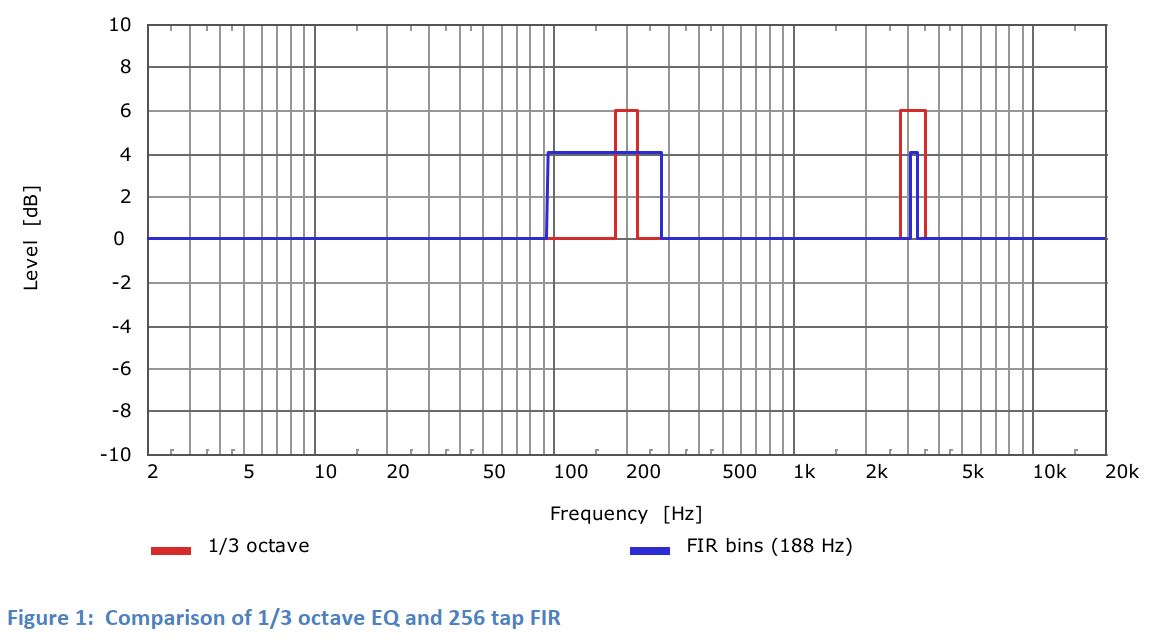
Figure 1 shows 1/3 octave bandwidth filters at 200 Hz and 3.15 kHz boosted 6 dB.
The frequency bins of a 256 tap FIR nearest to these are boosted 4 dB. It should be easy to see that on a log-frequency axis graph the FIR bins seem to
get bigger (wider) when they are located at lower frequencies. This a result of the log-frequency display since the FIR bins are all 188 Hz wide. It is actually the 1/3 octave filters that get wider at higher frequencies.
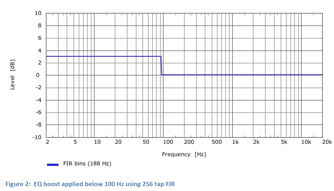
So what happens when we try to apply a level change below about 100 Hz? We can see this in Figure 2. Even though the left side of the graph only extends down to 2 Hz, the effects of the lowest frequency bin in the FIR filter extend down to DC. In fact, it actually extends even lower, to negative frequency, but that’s beyond the scope of this short article.
This is how an FIR filter can result in DC offset
Trying to apply level adjustment at frequencies lower than the bin size of the FIR can cause this. So how do we avoid it? Don’t allow the frequency range for FIR filter optimization to extend any lower than the frequency of bin 1 for the FIR filter. The frequency of bin 1 is the same as the bandwidth of the frequency bins.
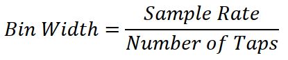
This can be calculated by dividing the sample rate divided by the number of taps.