Simple 1-zone paging system with Tesira and MICPAT-D
It is possible to make a simple paging system with a Tesira and MICPAT-D paging microphone. this is achieved by using simple logic connections between the two devices along with the microphone signal. Chimes can also be produced inside Tesira to pre-announce the paging message to the required zones.
In this example, the MICPAT-D is used to control paging of a single zone group to which a number of audio signals (or zones) can be assigned. The example in this design guide uses 12 zones but this can be reduced or increased.
Tesira custom block
A Tesira custom block is available to allow easy implementation of a 1 zone group paging system using Tesira and a MICPAT-D paging microphone. This example file allows for up to 12 zones to be assigned to the zone group. This example custom block can be downloaded below:
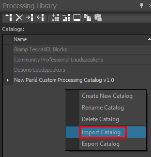
Once downloaded, this custom block catalog can be imported into the Tesira software by opening the Processing Library docking window, right clicking in the catalogs section and selecting Import Catalog.
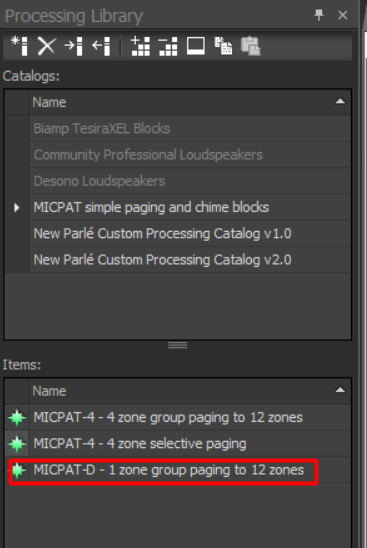
Then select the downloaded file. Three custom blocks will then appear in the new MICPAT simple paging and chime blocks area of the Catalogs section. For this application select the MICPAT-D - 1 zone group paging to 12 zones item and drag it into your Tesira design.
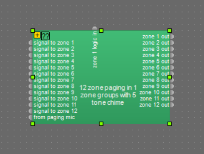
Once placed in a Tesira system design the custom block has 12 audio inputs, these are the 12 mono signals that would normally be fed to 12 zone outputs and may include any content and processing before the custom block. The 12 audio outputs from the custom block can be fed to the Tesira output blocks or further processing. One logic input to the custom block needs to be connected to a Tesira logic input block with one inputs. This logic input is then physically connected to a MICPAT-D paging microphone, see the 'Connecting MICPAT-D to Tesira section below for full details.
Custom block description
The main sections of the custom block are:
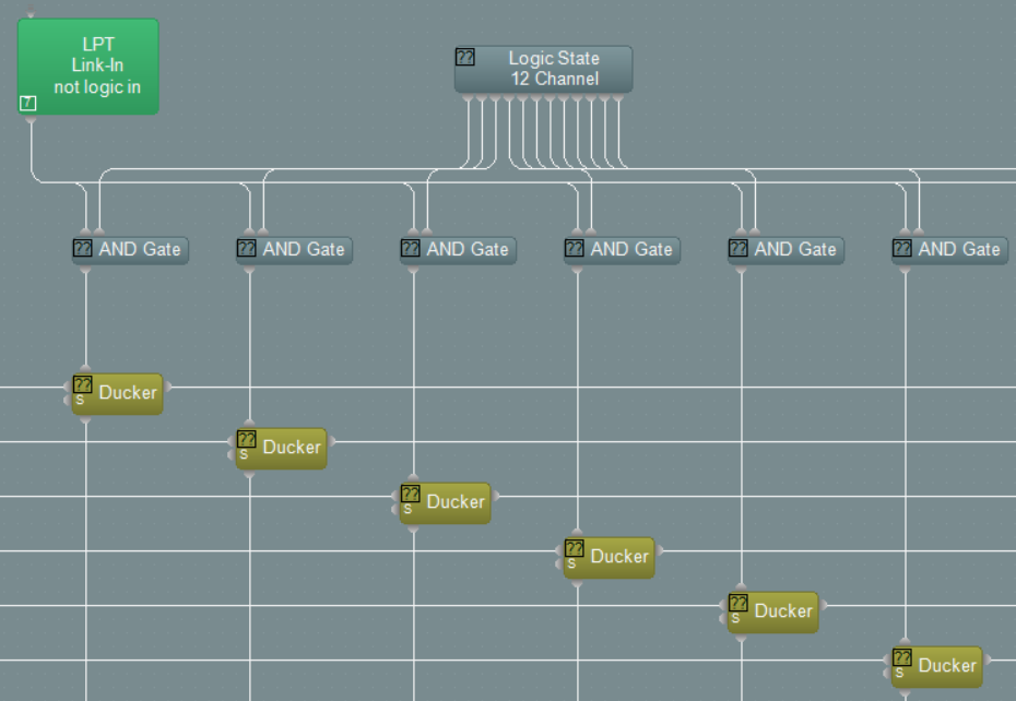
Muting the source audio during paging
Muting of the source audio is done by the use of 12 ducker blocks (one per zone) which are each controlled by a logic state switch and the logic input input, The logic state switches enable or disable each zone from the paging group, meaning they will or will not be part of the paging group. If all zones are required to be paged to then all logic state buttons should be ON. Zones which are not required to be paged should have their logic state button turned OFF. The attack time of the duckers are set to be very fast so that the source audio is muted immediately when paging starts. The release time is set to 2 seconds so that the source audio gradually re-appears once paging is finished
Generating the chime
The chime generator is made up of 5 different sine wave tones, each generated by a tone generator block. Each tone can have a unique frequency and duration from 0 to 6 seconds although 200-300ms is typical for a 5 tone chime. The time between each tone can be adjusted from 0 to 6 seconds although 0 is typical for a 5 tone chime. Each tone is generated by producing a logic signal for the tone duration which controls a ducker fed from a tone generator. The five tones are then mixed together and fed to the chime zone selector.
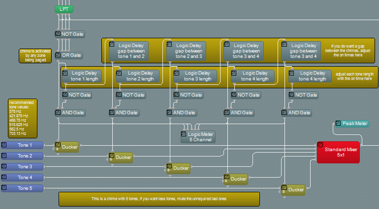
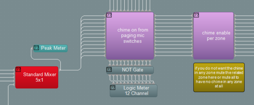
Chime zone selector
The generated chime is sent through a 12 way mute block with logic inputs control from the paging mic zone switches. It is possible to manually enable or disable the chime for each zone as required.
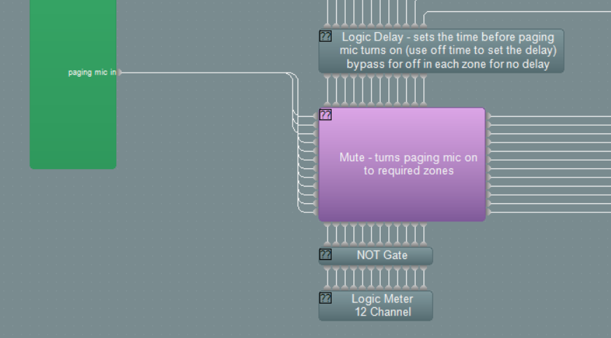
Paging mic zone selector
The audio from the paging mic is fed to a 12 channel mute block, controlled by logic inputs. The paging mic paging on switch is fed through logic delays before controlling the mute switches, this is so that the paging mic does not become active until the chime has been transmitted, this is done by adjusting the off delay time to be equal to or greater than the total chime length. It is also possible to set the off delay to zero so that the paging mic immediately becomes active in the selected zone. This may be required when no chime is required for example. The delay time of the paging mic can be adjusted on a per zone basis to follow the requirements of the system.
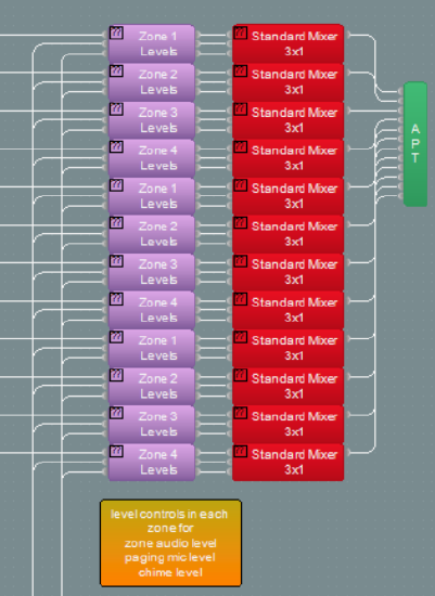
Mixing of the source audio, chime and paging mic
Simple three way mixers are used for each zone output, each fed from the source audio, chime signal and paging mic. This means that each signal can have a different level in each zone as required. These three signals are then fed to the output of the custom block to be further processed or connected to the Tesira output block.
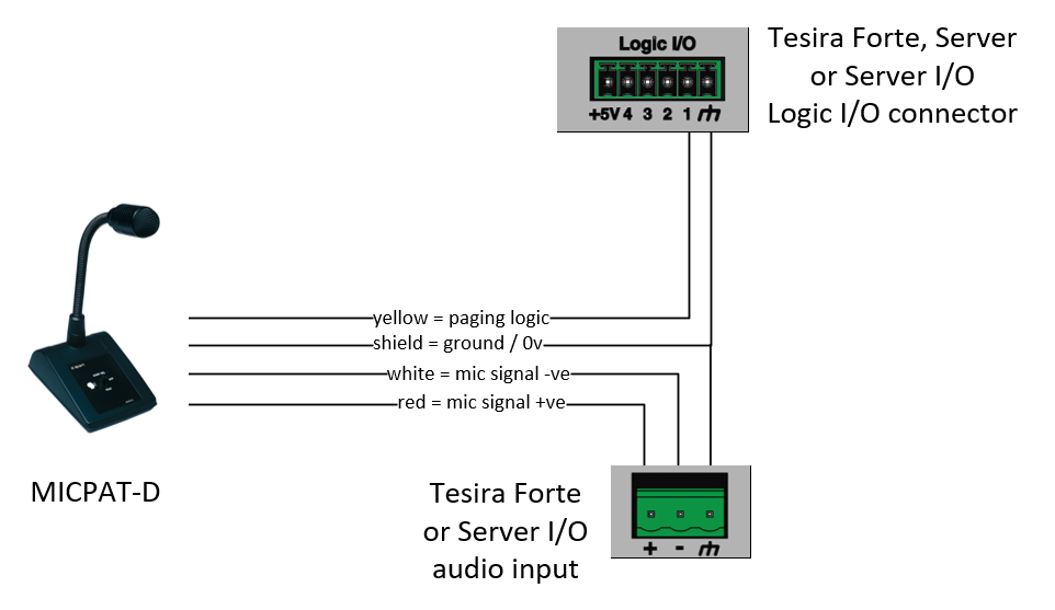
Connecting MICPAT-D to Tesira
The MICPAT-D is supplied with a 5 pin DIN connector on the captive cable. When connecting to Tesira this DIN connector is not required and can be removed. The following connections of the cores of the cable are required:-
Notes
- The MICPAT-D audio output is a mic level signal so the Tesira input block should be adjusted accordingly.
- Phantom power is not required by the MICPAT-D microphone.
- The MICPAT-D cable is 5 meters / 16.4 ft in length and should not be extended in this application.
- Only one MICPAT-D can be used in this application.
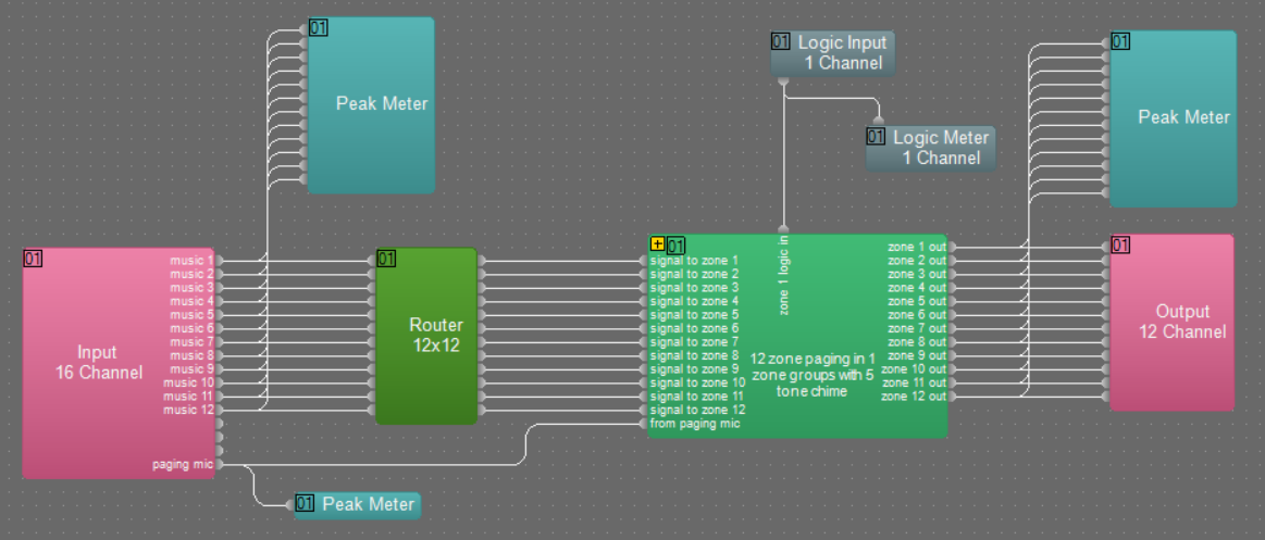
Simple example Tesira system design
In the simple Tesira system design below, inputs 1 to 12 , fed from 12 music sources, are connected to a router to allow music source selection per zone. The signals are then fed to the the custom block, which deals with the interface to the paging mic (connected to the logic input), chime generation, paging mic routing and music muting during paging. This sample file can be downloaded here.
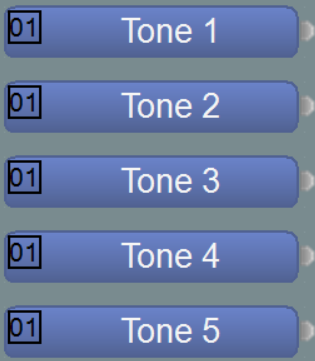
Chime settings
By default five tones are used to generate the chime signal. If only two tones are required, tone generators 3, 4 and 5 should be muted. Similarly if only three tones are required, tone generators 4 and 5 should be muted.
The frequency of the tones in the chime can each be set independently by adjustment of the associated tone generator blocks.
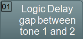
The length of each of the tones in the chime can each be set independently by adjustment of delay blocks marked Logic Delay Tone x Length.
The delay between each of the tones in the chime can each be set independently by adjustment of the delay blocks marked Logic Delay Gap Between Tone x and y.
Any frequency can be used for the tones but it is normally found that certain frequency combinations work together well. These are 375 Hz, 421.875 Hz, 468.75 Hz, 515.625 Hz, 562.5 Hz and 703.13 Hz.
MICPAT-D operation
Once connected and configured the operation of the MICPAT-D is very simple. A single two way 'Call' switch is fitted to the MICPAT-D, the lower position is not latching and therefore needs to be held in position when paging is required. The upper position is latching and therefore does not have to be held in position for paging to be active
Non latching - push to talk operation
The operator can push the 'Call' switch down and hold it down. At that point the chime will sound in all zones (so long as they are selected in the zone group selection area and chime is on to the zone in the above programming) and then the MICPAT-D paging microphone will become live into the all zones (which are enabled in the zone group selection area). Once the operator has finished the announcement they will release the 'Call' button and the paging process will end. Any selected audio which was present in the zone prior to paging will be re-introduced to the zone over a period of approximately two seconds.
Latching - push and release operation
The operator can push the 'Call' switch up and release, it will remain in that position. At that point the chime will sound in all zones (so long as they are selected in the zone group selection area and chime is on to the zone in the above programming) and then the MICPAT-D paging microphone will become live into the all zones (which are enabled in the zone group selection area). The paging mic will remain active until the 'Call' switch is returned to the centre off position at which point the paging mic will turn off. Any selected audio which was present in the zone prior to paging will be re-introduced to the zone over a period of approximately two seconds.