Simple 2-zone paging system using Tesira, EX-LOGIC, and MICPAT-2
A Tesira EX-LOGIC expander and MICPAT-2 paging microphone can be used to make a simple two-zone selective paging system. This is done using simple logic connections between the two devices along with the microphone signal. Additionally, chimes can be produced inside Tesira to pre-announce the paging message to the required zones.
Equipment List:
- Tesira Forte / Forte X / Server I/O
- EX-LOGIC (connection via ports 13-16 required)
Design Note: This design wiring topology only supports the MICPAT-2 used with an EX-LOGIC.
Tesira custom block
A Tesira custom block allowing easy implementation of a two-zone paging system using Tesira and a MICPAT-2 paging microphone can be downloaded here:
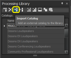
Once downloaded, this custom block catalog can be imported into the Tesira software by opening the Processing Library docking window, right-clicking in the catalogs section, and then selecting Import Catalog. The custom block uses a .tlf file extension.
MICPAT simple paging and chime blocks.tlf
After downloading, select the file. Three custom blocks will appear in the new MICPAT simple paging and chime blocks area of the catalogs section. For this application, select the MICPAT-4 - 4 zone selective item and drag it into your Tesira design.

Once it's placed in a Tesira system design, the custom block has four two inputs. These are the mono signals that would normally be fed to four zone outputs and may include any content and processing before the custom block.
The audio outputs from the custom block can be fed to the Tesira output blocks or further processing. Two logic inputs to the custom block need to be connected to a Tesira logic input block with two inputs. These logic inputs are then physically connected to a MICPAT-2 paging microphone.
See the 'Connecting MICPAT-2 to Tesira' section below for full details. Ensure the logic input port assignment is paired properly with the field wiring.

Custom block description
The main sections of the custom block are:
Muting the source audio during paging
This is done by using two ducker blocks (one per zone) controlled directly from the two-zone logic inputs. The attack times of the duckers are set to be very fast so that the source audio is muted immediately when paging starts. The release time is set to 2 seconds so that the source audio gradually re-appears once paging is finished.

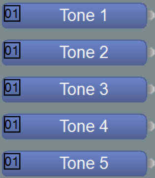
Generating the chime
The chime generator is made up of five different sine wave tones, each generated by a tone generator block. Each tone can have a unique frequency and duration from 0 to 6 seconds, although 200-300ms is typical for a 5-tone chime. The time between each tone can be adjusted from 0 to 6 seconds, although zero is typical for a 5-tone chime. Each tone is generated by producing a logic signal for the tone duration, which controls a ducker fed from a tone generator. The five tones are then mixed together and fed to the chime zone selector.

Chime zone selector
The generated chime is sent through a 2-way mute block with logic inputs control from the paging mic zone switches. The chime can be manually enabled or disabled for each zone.

Paging mic zone selector
The audio from the paging mic is fed to a two-channel mute block controlled by logic inputs. The two-paging mic mute switches are fed through logic delays before controlling the mute switches. This is done so that the paging mic does not become active until the chime has been transmitted. This is enabled by adjusting the off-delay time to be equal to or greater than the total chime length. It is also possible to set the off-delay to zero so that the paging mic is immediately active in the selected zone. This may be required when no chime is needed. The delay time of the paging mic can be adjusted on a per-zone basis to follow the requirements of the system.

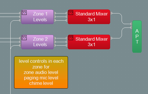
Mixing of the source audio, chime, and paging mic
Simple three-way mixers are used for each zone output, as well as each fed from the source audio, chime signal, and paging mic. This means each signal can have a different level in each zone as required. These three signals are then fed to the output of the custom block to be further processed or connected to the Tesira output block.
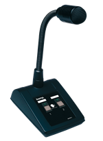
Connecting MICPAT-2 to Tesira
The MICPAT-2 has a 5M attached 6-wire connection and offers a balanced microphone level output and two separate paging contacts with led indication. The color code chart is listed below.


Notes:
- The MICPAT-2 audio output is a Mic-level signal, so the Tesira input block should be adjusted accordingly. Phantom power is also not required by the MICPAT-2 microphone.
- The MICPAT-4 cable is 5 meters / 16.4 ft in length and should not be extended in this application
- Only one MICPAT-2 is shown used in this application. Up to 2 MICPAT-2 devices may be used per EX-LOGIC.
- EX-LOGIC ports 13-16 must be used for proper LED and Logic input triggering.
A simple example of Tesira system design
In the simple Tesira system design shown below, inputs 1 to 4, fed from 4 music sources, are connected to a routed to allow music source selection per zone. The signals are then fed to the custom block, which deals with the interface to the paging mic (connected to the four logic inputs), chime generation, paging mic routing, and music muting during paging. This sample file can be downloaded here.

The equipment list is populated with TesiraFORTE AI and EX-Logic. A server-level device may be substituted per application needs. The logic input block is set to fixed in unit with device I/O selected to match the attached wiring diagram.
Chime settings
By default, five tones are used to generate the chime signal. If only two tones are required, tone generators 3, 4, and 5 should be muted. Similarly, if only three tones are required, tone generators 4 and 5 should be muted.
The frequency of the tones in the chime can each be set independently by adjustment of the associated tone generator blocks.
The length of each of the tones in the chime can each be set independently by adjustment of delay blocks marked Logic Delay Tone x Length.
The delay between each of the tones in the chime can each be set independently by adjustment of the delay blocks marked Logic Delay Gap Between Tone x and y.

Any frequency can be used for the tones. However, certain frequency combinations work together well. These are 375 Hz, 421.875 Hz, 468.75 Hz, 515.625 Hz, 562.5 Hz and 703.13 Hz.
MICPAT-2 operation
Once connected and configured, the operation of the MICPAT-2 is very simple.
Zone paging
The operator can select the zones to be paged using any combination of the two buttons for momentary push-to-talk paging. The selected buttons will be illuminated until released. The MICPAT-2 microphone will be active while LEDs are lit and routed to appropriate zones per the buttons used.
Push talk button 1, 2, or both buttons to talk and keep the switch(es) pushed in as long as you talk.
Talk into the microphone at a distance of 5 to 20 cm, depending on the loudness of your voice and the gain setting of the connected Tesira input block.