Three Story Office Building Phase 1 (Sound Masking and Paging)
This system design template shows how Vocia products can be easily integrated with Qt Pro Sound Masking Systems to create a simple multi-zone paging system. Vocia is a highly reliable solution that provides scalable, flexible and excellent audio quality while managing all your paging and background music requirements. Used in conjunction with a Qt Pro Direct Field Active Emitter Sound Masking solution results in a consistent, comfortable and even distribution of both ambient sound and paging throughout the space.
Take the example of a three story office building that is transitioning or adding a sound masking and paging system, with the installation taking place over multiple phases. This upgrade will transition from a basic multi-zoned paging system through integrating the building's existing VoIP network to support paging and adding background music to selected areas. This article details the requirements for phase 1: the sound masking system with a relatively simple paging system. In Phase 2, We will add more paging zones and integrate the building's existing VoIP network to support paging from any phone. Later, Phase 3 will add background music and remote control per floor.
System design
Sound masking and paging system functionality scope: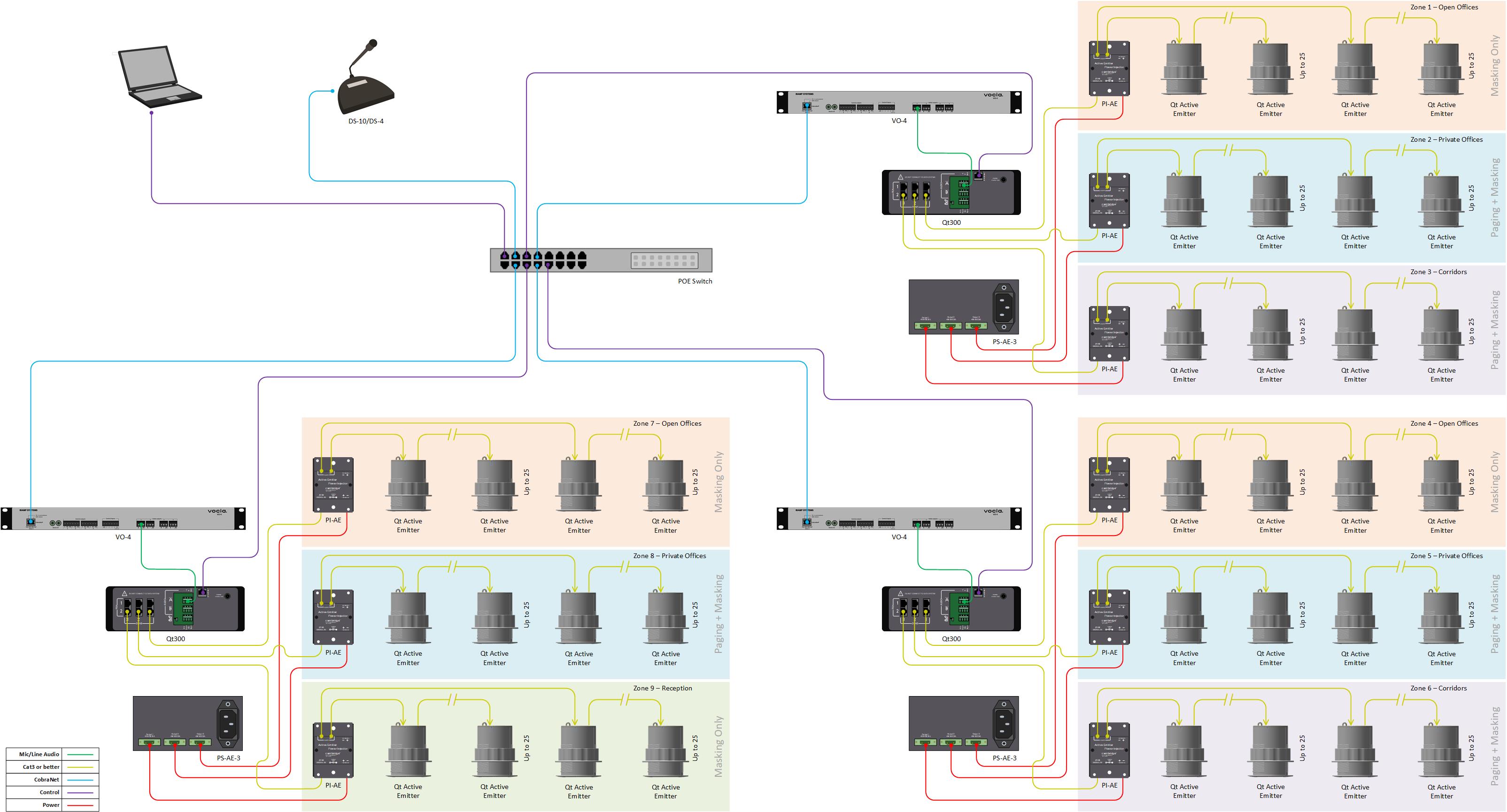
- 3 Sound Masking zones per floor to accommodate
- Open office spaces
- Private offices
- Corridors and common areas
- 1 Paging Station to provide live paging from the reception area
- 3 Paging Zones capable of receiving the same, or unique pages
Equipment list
Below is the list of Biamp Vocia and Qt Pro equipment used in this project:
- 1 - DS-10: 10-button desktop paging station
- 3 - VO-4: 4-channel analog output
- 3 - Qt300: 3-zone sound masking generator
- 3~6 - PS-AE-3: Qt Active Emitter Power Supply w/3 Output Ports
- 9~18 - PI-AE: Qt Active Emitter Power Injector (25 Qt AE per port x 2 each)
- Up to 225 EPW-16-4: Qt Active Emitters (4 Pack of Qt Active Emitters with 16ft Cables/White)
Notes:
- Optional Qt Active Emitter mounting accessories, black emitter color, and various cable lengths are also available.
- Other non-Biamp equipment is required, including the CobraNet PoE network switch.
Example files
The example file for this system design template is set with 3 zones to cover each floor independently: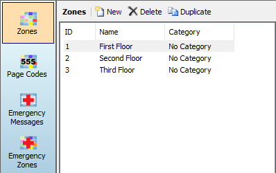
- Paging zone 1 - First Floor
- Paging zone 2 - Second Floor
- Paging zone 3 - Third Floor
Four page codes have been provided to allow for flexible paging throughout the zones. 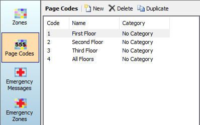 As each DS-10 has 10 buttons, we will utilize Button Based Assignment for the page codes:
- Page Code 1 - Supports live paging to the first floor
- Page Code 2 - Supports live paging to the second floor
- Page Code 3 - Supports live paging to the third floor
- Page Code 4 - Supports live paging to all floors at a higher priority
*For more information about paging priority, see the Priority Levels section of the Vocia help document.
File Download: Three Story Office Building Phase 1 (Sound Masking and Paging)
Networking details
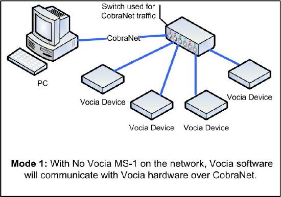 Vocia supports two modes of network communication depending on the network topology. One requires a direct connection to a CobraNet network while the other requires an IP-based connection to the MS-1e Message Server to access the system. Since this system does not include an MS-1e, the first method will be used. The system is also small enough that an isolated network with PoE will suffice for CobraNet communication and audio transport between Vocia devices.
Setup Requirements:
- Network switch with sufficient ports for CobraNet connections and Qt Pro Controllers
- 802.3af (Class 2) PoE Injector for powering the DS-10 paging station (unless the CobraNet switch provides PoE).
- 802.3af (Class 3) PoE Injector for powering the VO-4 analog outputs (unless the CobraNet switch provides PoE).
Setup Requirements for Qt Pro Controllers :
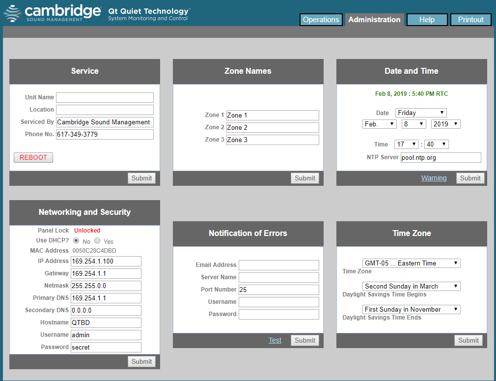 Qt Pro Controllers are set to DHCP by default. If no DHCP server is present on the network they will default to 169.254.1.1. When using multiple Qt Pro controllers it's necessary to set individual, fixed IP addresses to each device in the link local range. To accomplish this, follow this steps:
- Connect one Qt Pro controller to the network (alternatively, a PC can be connected directly to the network port on the Qt Pro Controller)
- Open a web browser and navigate to 169.254.1.1
- A login promt will appear to access the Qt Pro Controller. Default credentials are:
- Username: admin
- Password: secret
- Navigate to the Administration tab
- Under Networking and Security change "Use DHCP" to No
- Change the IP Address to an address in the link local range (169.254.x.x) - each Qt Pro controller should have a unique IP address
- click Submit
- Repeat steps 1~7 with each Qt Pro Controller in the system
System setup
Both the outputs of the VO-4 and the inputs of the Qt300s are set, by default, at +4dBu and all Vocia devices are set to unity gain. This allows the system to start working, once the file is loaded in Vocia and some minor adjustments in the Qt300. While some adjustments can be made directly from the front panel of the Qt300, it's recommended doing them thru the MCS Master Control via web browser:
 Connect to the Qt300 by opening a web browers and navigating to the Qt300 IP Address
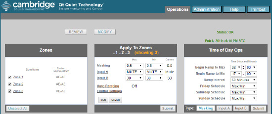
- Under Operations, select Modify
- Under Zones, select the zones that will use Qt Active Emitters. If all Zones will use Qt Active Emitters, click Select All on the bottom left corner
- Under Apply to Zones, click Emitter Settings
- Change the Emitter type to Active Emitter and Masking Spectrum to Qt Active
- Click Submit and then Back
- For each zone, set the required masking level
- Set audio input level A in each Sound Masking Zone according to this table:
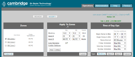


| Floor |
Sound Masking Zone 1 Audio Input A Level |
Sound Masking Zone 2 Audio Input A Level |
Sound Masking Zone 3 Audio Input A Level |
| Qt300 First Floor | Mute | 25 | Mute |
| Qt300 Second Floor | 25 | 25 | Mute |
| Qt300 Third Floor | 25 | 25 | Mute |
- Repeat steps 1~8 for each Qt300 Controller
- Check and confirm adequate DS-10 microphone input level from the Audio & Live Control tab found under DS-10 properties
- If needed, paging output for all Sound Masking Zones in the Paging Zone can be adjusted from the Audio & Live Control tab found in the corresponding VO-4 properties. If changes are needed on a particular Sound Masking Zone, Adjust the appropriate analog input level for the Sound Masking Zone in the corresponding Qt Controller