Restaurant with 3 zones
This system design template shows how Tesira products can be used in a typical restaurant installation.
The system is intended to be used for background music (BGM) playback to create the atmosphere within the restaurant for good customer experience. BGM source selection and level control are available for each zone independently. Alongside lobby and public space with a bar, it is also not uncommon for restaurants to have private dining rooms where customers expect to have the opportunity of playing music from their own sources, i.e. smartphones.
In this example, the restaurant layout contains three zones: a lobby, a public space with a bar, and a private dining room with connectivity for a user source. Each zone is outfitted with distributed ceiling speakers for BGM music playback. Selection of two background music sources and zone output level control are available independently for the lobby and for the public space with a bar. The settings for both these zones are made from a single wall mount control panel installed in the lobby. Selection of three background music sources (two common sources and the user source) and zone output level control are available in the private dining room on a separate wall mounted panel installed in the room itself.
Room design
Room Functionality Scope:
- Selection of two common background music inputs in each of the three zones
- Auxiliary input for user source in private dining room via a wall plate with two XLR analog connectors
- Constant voltage distributed ceiling speaker feed in each zone for BGM sources playback
- Source selection and output level control via wall mounted TEC-1 panels
- Logic inputs to trigger system mute to all zones via third-party fire alarm system contact closure
Equipment list
Below is the list of Biamp equipment used in this project:
- 1 - TesiraFORTÉ AI 12 mic/line level inputs; 8 mic/line level outputs with integrated USB audio
- 2 - Tesira TEC-1i/TEC-1s Tesira PoE Ethernet control device, in-wall/surface mount
- 2 - AMP-A460H 4-Channel, 60W class D amplifier, supports both 70V and 100V constant-voltage speaker systems
- Desono CM60DTD 6.5" two-way, thin edge ceiling loudspeaker, with back can. 70V transformer power taps in watts 60-30-15-7.5-3.75. (Quantities as needed to meet project scope)
Note that other non-Biamp equipment is required, including background music sources, 2 x XLR wall plate, network switch, 802.3af (PoE) Class 1 injectors for wall panels, and fire alarm panel interface.
Example file
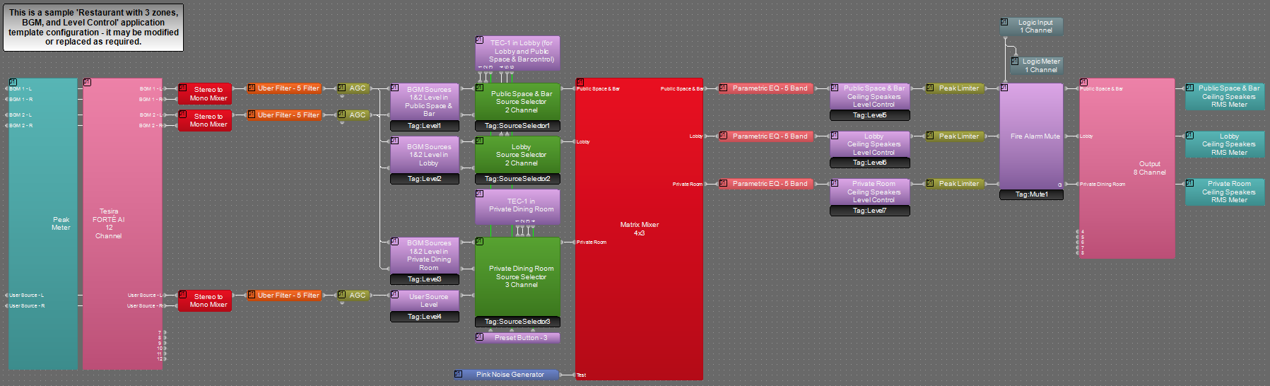 The example file for this system design template is set up with all the audio I/O, processing, and control points required, and is ready to load to the system and begin setting up the room gain structure. In the file, the matrix routing is already in place to support the project design requirements.
Three stereo sources (two common stereo BGM sources and the user source via wall plate) are connected to TesiraFORTÉ AI inputs 1-6. Signal mixes for each of the 3 zones are routed to TesiraFORTÉ AI outputs 1-3 that feed constant voltage amplifier channels and distributed ceiling speaker systems in each zone. Source Selector blocks control BGM sources selection in each zone. TEC-1 panel blocks contain simple menu for source selection and zone output volume control for easy access by the customer.
The file's Equipment Table is populated with the proper hardware to match the layout but will need to have serial numbers assignments added before loading the file to the system.
The .zip file below contains the example Tesira configuration files for this restaurant application.
File Download: Restaurant_with_3_zones_BGM_Level_Control.zip
Networking details
The restaurant application will make use of only Control network interface of the Tesira FORTÉ AI. This system is small enough to be placed on a very small local AV switch but is also equally capable to be integrated into a larger building network sharing larger switches for control traffic. For a more detailed guide on available Tesira system network topologies in a larger range of network applications, it would be helpful to reference our Tesira Network Infrastructure article.
TesiraFORTÉ AI Control port, TEC-1 Ethernet ports, control PC Ethernet port should be connected to the control network switch, and these ports IP addresses should be on the same subnet. Tesira FORTÉ AI device will need to be discovered in Tesira software before the configuration can be sent. The default network configuration of TesiraFORTÉ AI and TEC-1 units is DHCP, so if there is no DHCP server on the network the units will revert to Link Local addressing (169.254.xxx.xxx, netmask 255.255.0.0) schemes. More details on the initial connection to the system can be found in TesiraFORTÉ Quickstart article.
To check TesiraFORTÉ AI network settings, you can use the display on the front panel of the device. To check TEC-1 network settings, you can discover the units via the software (video TEC-1 Setup (Software)) or access menu from the TEC-1 display via the locksmith pins on the back of the unit (video TEC-1 Setup (Manual)).
For the configuration to work properly on TEC-1 devices, Device IDs in TEC-1 software blocks should be checked to match Device IDs of the actual devices on the network.
Setup Requirements:
- Control network switch with sufficient ports
- 802.3af (Class 1) PoE injectors for powering the TEC-1 panels (unless the Control switch provides PoE power). TEC-1 requires 3.2W @ full display utilization
After these control network setup steps are complete, you will be ready to send your compiled system configuration to the hardware.
Audio setup
- Follow Gain Structure best practices to set input and output levels of BGM sources. Input and output gain levels have been left at default settings for integration flexibility of the file. Input and output metering has been added to assist with setting gain structure within the file. Additional meters can be added to the file as required to allow for detail at a point along the signal path.
- Connect two common BGM sources stereo outputs to TesiraFORTÉ AI inputs 1-4.
- Connect wall plate in private dining room to TesiraFORTÉ AI inputs 5-6. User’s personal device will most likely have a 3.5mm Stereo Mini-Jack connection, so it is recommended that a proper Y-cable is provided in the private dining room to allow for a user device to be connected to the wall plate. Please refer to the article Wiring audio inputs and outputs (Stereo Unbalanced Line Input section) for information on how to prepare such a cable.
- The three stereo sources channels L and R are mixed into mono internally in Tesira with help of 'Stereo to Mono Mixer' blocks.
- Be sure to set constant voltage (CV), Bridge on and HPF switches on the AMP-A460H amplifiers' channels to ON to support the project speaker type. Refer to the system diagram above for more details.
- Level and mute controls have been added to the file pre and post matrix mixer. These are added for flexibility to meet the design criteria and tastes of the client or integrator. Upper and lower limits have been added to level blocks for user-facing controls. These can be adjusted to fit the design application as needed.
- Uber Filters and AGC blocks have been added to all signal paths to allow for any additional equalization and automated signal dynamics management. Additional filtering or dynamics blocks may be added or changed as needed to achieve the desired results in the file.
- Parametric EQ blocks have been added to all speaker outputs to allow for tuning and equalization in each zone. For a more detailed guide on sound system optimization, we have provided Equalizing loudspeakers in a sound system article.
- Changes to matrix mixer can be made as needed to allow for alternative routing of signals, as well as routing of additional signals that may be connected to the system as a part of future expansion.
- Two TEC-1 panels provide access to source selection and control of output level in each zone. The set of functions available from TEC-1 panels can be modified to fit the design application as needed.
- Logic for fire alarm muting is set up to mute all audio output paths for the duration of the contact closure being low. This functionality may be modified to fit exact room requirements, or removed if not needed.
Control system integration
The example Tesira configuration file for this application has been set up to allow third-party control systems to easily control the Tesira system. There are control points for Source Selection, Level, and Mute already in place to allow for you to use it as-is, or control points can be added as needed to suit the requirements of the client. Control points within the file have been noted with an additional text box showing their Instance Tags. These tags can be changed as needed to suit the programmer workflow or standardization.
Fire alarm integration
 In this application, we have added logic to control muting of the system on a contact closure from the fire alarm or other systems. In the sample configuration file, audio outputs to all three zones will be muted for as long as TesiraFORTÉ AI GPIO contact #1 is in a low state. This logic is an optional feature of the file and may be removed if not needed.
For instructions on how to wire the relay to the GPIO please review the Wiring LED's and relays to the EX-LOGIC article.
When connecting this fire alarm wiring to a Tesira system, it is important to know whether the switch is normally-open or normally-closed.
On the TesiraFORTÉ AI logic input, a short circuit will create a low logic signal (logic OFF), and an open circuit will create a high logic signal (logic ON). Therefore, normally-closed mute switches create normally-low logic signals, and normally-open mute switches create normally-high logic signals.
So, if you are working with normally-open switches, you'll usually need to either put the logic signal through a NOT gate or just enable the Invert button in the Logic Input block (please see illustration at the right).
It is important to note that in the provided configuration the fire alarm contact closure will mute the output audio paths to all zones to allow audio from separate fire alarm or EVAC system speakers to be heard. The provided configuration does not have a path for an announcement from those systems to be played over the Tesira system speakers. This functionality may be added to the file if needed.