Microphone placement: specs and patterns
This article describes some of the physical placement considerations for microphones in a conference environment.
Sensitivity
Microphone sensitivity is a physical characteristic of a microphone. It describes the output voltage of the microphone in response to sound.
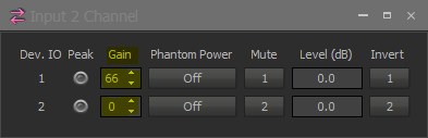
The "Gain" setting in the DSP Input block defines the amount of analog pre-amp gain or input gain which is applied to the mic input channel. This input gain changes the sensitivity of the input to the electrical impulses generated by the microphone capsule. A higher input gain value is more sensitive to small electrical signals than a low input gain value. Microphones typically have very low output voltages, especially compared to line level devices such as a CD player or tuner, or a DSP output.
The voltage generated by the mic capsule is directly related to the amount of motion the diaphragm makes in response to variations in air pressure. Variations in air pressure are perceived by our ears as sound.
Mics and speakers
Microphones and speakers are very similar mechanically. Electric current provides changes in voltage in the voice coil of a speaker creating an electromagnetic field which moves the speaker cone and generates sound. On a microphone the sound moves the diaphragm of the mic capsule, generating electric current by disrupting the local electromagnetic field.
If you turn the volume down on an amplifier connected to a speaker, the speaker gets quieter. There is less electric current to move the speaker cone to push the air and generate sound waves. To hear the speaker you need to move closer. If the volume is turned up high you can move further away and still hear the sound.
A microphone works in much the same way but it is listening instead of speaking. If the DSP has low input gain applied to the microphone's input then the talker may need to get very close to the microphone to be heard. Quiet noises or sounds that are happening farther away may be hard to hear. If the DSP input gain is turned up (increasing sensitivity) it becomes easier to hear the talker. At the same time it also becomes easier to hear quieter noises in the background, whether they are noises coming from farther away or are ambient noises around the microphone.
For every 6dB of added input gain the sensitivity of the microphone is (roughly) doubled.
Coverage patterns
Microphones and speakers both have specific coverage patterns based on their design. A coverage pattern indicates the physical area surrounding the device over which it is usable. There are a variety of standard coverage patterns for microphones.
Coverage patterns are variable with respect to frequency, that is, the sensitivity will be different at one frequency than at another frequency. The chart shows the difference in dB-SPL.
A microphone or speaker will sound different if you stand in one place versus another relative to it due to the variation in dB-SPL sensitivity. The effective working angle of coverage for a mic or speaker is defined as being within the "6-dB down point", this is the off-axis angle at which the device is within 6dB of the on-axis measurement (the 0-dB reference). A 6dB difference is audible to most listeners.
Coverage patterns are shown by polar plot charts, these charts allow you to visualize the behavior of the device based on where you are located relative to it. The device is at the center of the plot pointing toward the 0 degree axis. As sensitivity (microphone) or volume (speaker) increases the coverage area expands but the shape of the pattern remains the same.
Polar plots will typically have more than one pattern drawn. Each pattern is unique for a different frequency (the chart will be labeled with the frequencies). Variations in sensitivity are shown as rings on the circular chart and the scale will be labeled - typically it will be 3dB or 6dB per division. Note that polar plots do not show distance. Polar plots are concerned with patterns. The size of the pattern is a variable, the shape is a constant.
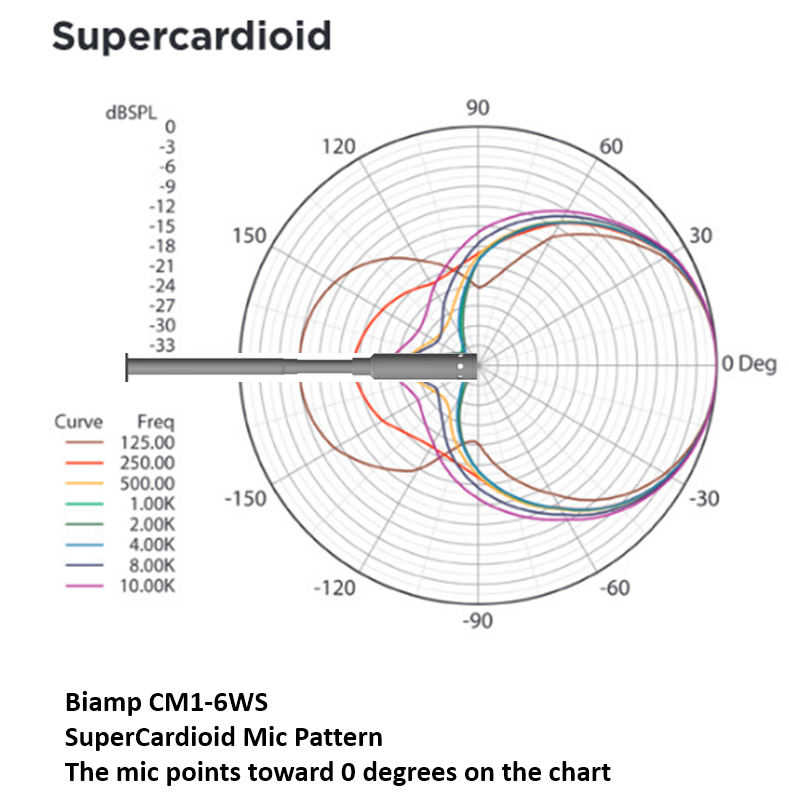
The 6-dB down point for the SuperCardioid mic is at about 45 degrees off-axis. You can see the difference in response patterns as frequency goes from high (10kHz) to low (125Hz). At 10kHz there is almost complete rejection behind the microphone, while at 125Hz it yields a figure-8 pattern, with 18dB of attenuation behind the microphone.
Microphone data sheets will normally have a single polar chart showing multiple frequency plots, occasionally they are provided as a set of polar charts with a single frequency on each. For loudspeakers there are typically 2 polar charts, one for horizontal coverage patterns, another for vertical coverage patterns, This is due to the presence of multiple drivers in an average speaker enclosure. The 2 patterns will not be identical.
A speaker allows you to easily experiment with coverage patterns and hear what they sound like. If you are directly in front of a speaker you are said to be "on axis" with it. This is typically the optimal listening area for the speaker. As you move to the side you are moving "off axis" and away from the best sounding placement. The further you move off axis the more noticeable the change in tone will be, as you move around behind the speaker the high-frequency component of the sound becomes quieter and the overall sound you can hear is less accurate than what you heard on-axis. Lower frequency tones will not be affected as much as you move behind the speaker. This difference in behavior between the high frequency and low frequency components of the audio spectrum is clearly of great interest and concern to us when we position the speaker.
Placement
Now that we have a better understanding of coverage patterns and their interaction with the frequency response of a mic or speaker it is possible to look at placement options. With microphones the goal should always be to place the mic as close to the talker as possible. This will maximize the signal to noise ratio and give the best sounding results. The farther the mic is from the talker the higher the pre-amp gain needs to be, increasing the amount of ambient and background noise picked up by the microphone.
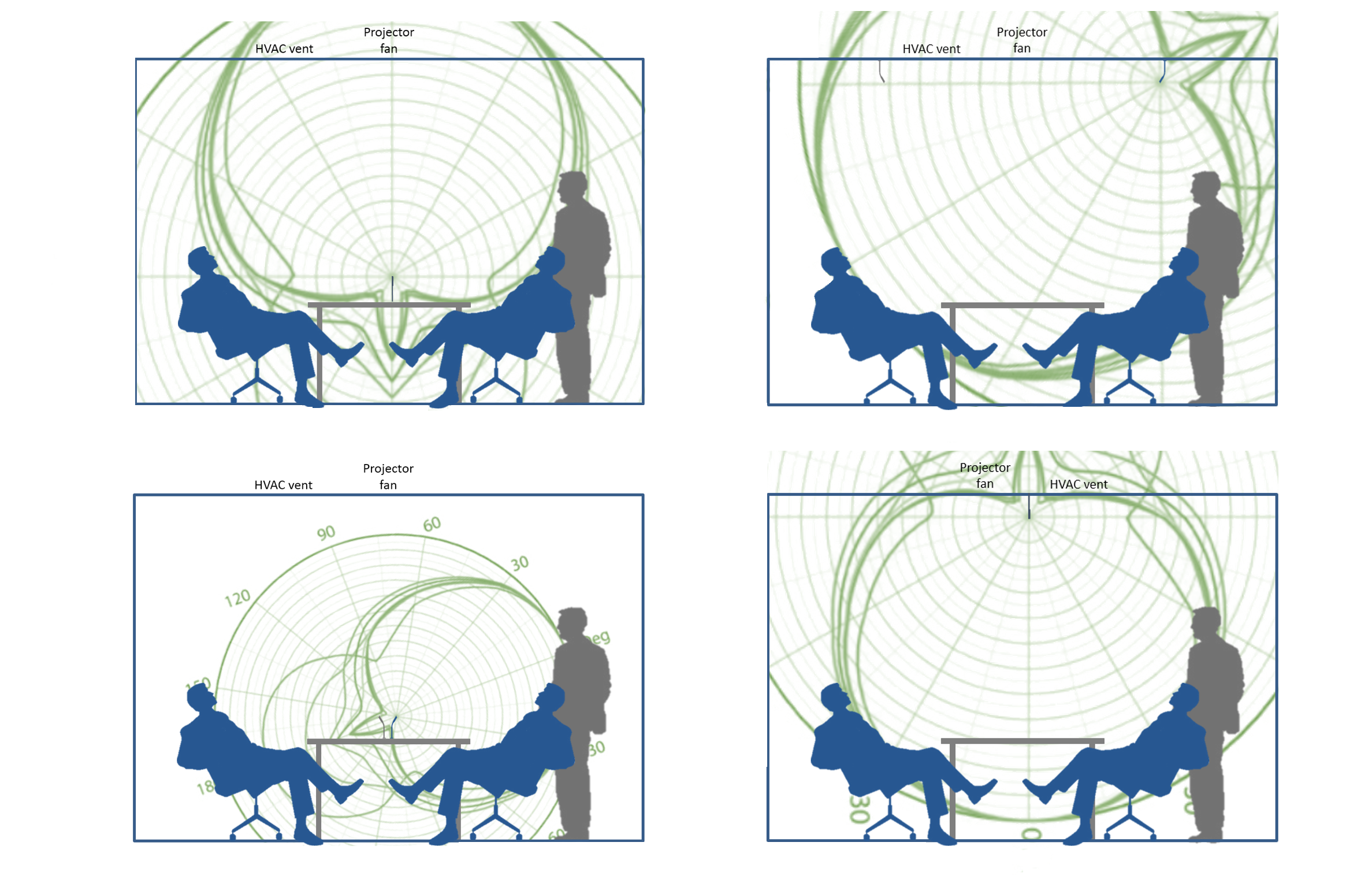
The image above shows four placement options for a SuperCardioid mic, showing the resulting coverage pattern. Input gain is adjusted as necessary to hear the talker at the same level for each mic position. In many situations two (or more) mics close to the talkers will sound better than one "room mic".
In three of the cases illustrated above the HVAC vent and projector fan sounds will be in direct competition with the talker. In some cases they are 30 to 40dB "closer" to the mic. That means that even a very quiet fan could overwhelm the spoken word.