Power over Ethernet (PoE)
Power over Ethernet (PoE) was originally developed to provide power along with data to locations where AC power would be inconvenient, expensive, or infeasible to install.
However, even in situations where AC power is feasible, PoE offers some extra advantages:
- Data and power are confined to a single cable, which means cabling requirements are reduced.
- Existing network infrastructure can be used in most cases.
- PoE is simple to set up and does not require a qualified electrician to install because it operates at a low voltage.
This article provides basic information on PoE operation and specification.
The terms PoE and PoE+ have some overlap in meaning (as explained in the PoE and PoE+ standards section). For this reason, PoE and PoE+ equipment will be generically referred to as “PoE equipment” throughout this article.
PD and PSE definitions
In a PoE-powered system, there are always two types of devices: one that supplies power, and one that consumes power. In the language of the PoE standard, these are referred to as the Powered Device (PD) and the Power Sourcing Equipment (PSE):
PD (Powered Device) – a device that is connected to a PSE and negotiates its power needs with it. It is considered a power load.
PSE (Power Sourcing Equipment) – a device that negotiates power provision with the connected PD. It is considered a power source.
PSE types
There are three main types of PSE in use today, all are compatible with Cat5e or higher category cable. PSE type is chosen based on the existing infrastructure and the number of PoE devices that will eventually be connected.
PoE Switch (Endspan)
A PoE switch looks like an average Ethernet switch, however, it provides an all-in-one device for data switching and power provision. Typically, this is the most flexible and economical solution, especially if new networking hardware is required and multiple PD's need PoE.

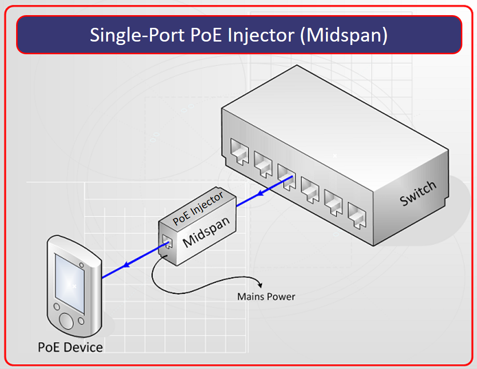
Single-Port PoE Injector (Midspan)
A Single-Port PoE Injector (Midspan) is designed to be used in-line with the Ethernet cable to provide power to a single device. It suits applications where there aren't enough PoE devices to warrant the cost of a PoE switch, or if the data needs to first be transmitted a long distance (e.g. via fiber), before being converted back to copper cabling, and then have PoE applied.
The downside to using a Single-Port PoE Injector is the requirement for a mains outlet to operate, and the tendency to become costly when more than a few devices require power.
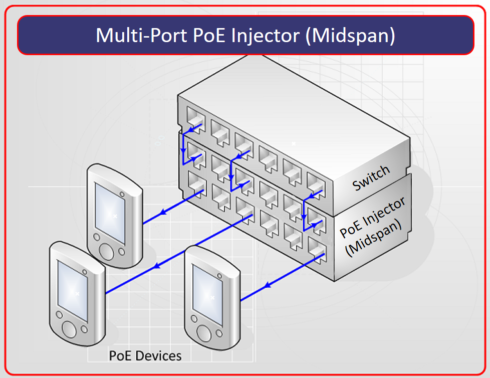
Multi-Port PoE Injector (Midspan)
The Multi-Port PoE Injector (Midspan) was developed to “inject” power into an existing Ethernet network where the Ethernet switch does not provide PoE capability. The Multi-Port PoE Injector box sits between an existing Ethernet switch and the PoE devices.
PoE and PoE+ standards
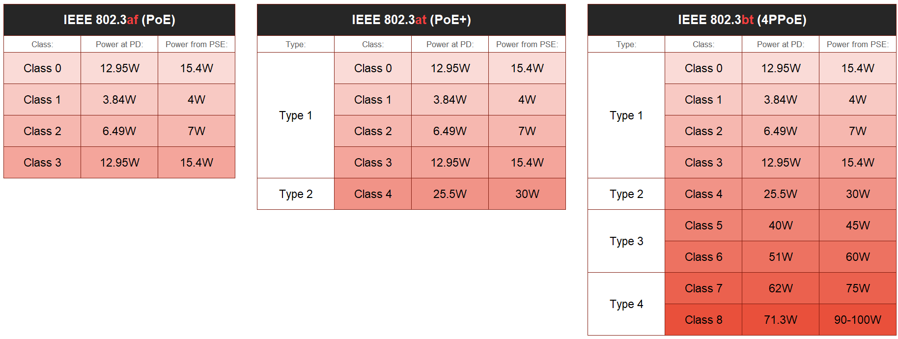
Power is provided to a PD based on its class. There are two IEEE standards that define the PoE classes:
IEEE 802.3af-2003 standard is commonly known as "PoE". It defines PoE Classes 0-3, with maximum power at PD being 12.95W.
IEEE 802.3at-2009 standard is commonly known as "PoE+" or "PoE Plus" and it is the later update to the IEEE 802.3af-2003 "PoE" standard. It defines PoE Classes 0-4, where Classes 0-3 are incorporated from the older 802.3af "PoE" standard under "Type 1", and "Type 2" only includes Class 4 with maximum power at PD being 25.5W.
IEEE 802.3bt-2018 is named "4PPoE". It incorporated Classes 0-4 from the earlier standards and adds "Type 3" (Classes 5-6) and "Type 4" (Classes 7-8) with maximum power at PD being 71.3W.
The IEEE 802.3af "PoE" standard was not discontinued after the introduction of the IEEE 802.3at "PoE+" standard, and both standards were still in use. This created confusion about what the terms "PoE" and "PoE+" exactly mean. Many publications informally use “PoE” to refer to Class 0-3 and “PoE+” to refer to Class 4 only. But as mentioned above, the 802.3at "PoE+" standard includes Classes 0-3 from the older 802.3af "PoE", so "IEEE 802.3af PoE Class 2" and "IEEE 802.3at PoE+ Type 1 Class 2" are two different but correct ways to say the same thing – that a device requires 6.49W of Power over Ethernet. Perhaps even more confusingly, the term "PoE" is often used to refer generically to the overall concept of transmitting power over an Ethernet cable, regardless of how much power is being transmitted or which standard is being used.
We recommend additional research when a device specification only claims PoE, PoE+, or 4PPoE but does not give enough information on the device's power requirements. The PoE+ or 4PPoE class and/or the exact power draw value must also be provided. Biamp product families include PoE devices of Сlasses 0-4. Please use documentation to verify the power requirements for each device.
Please also see the Specifying PoE switches for Biamp Tesira devices article for recommendations on PoE network design for Tesira PoE devices.
PoE negotiation
If a PD is connected to the PSE, it undergoes a PoE negotiation procedure before it can receive the needed power for operation. The PoE negotiation procedure is defined by the IEEE 802.3af/at standards. Also, non-PoE devices will not be damaged if they are connected to a PSE due to this procedure.
PoE negotiation is comprised of three stages: discovery, classification and operation.
Discovery
PSE leaves the Ethernet port unpowered and periodically checks if something has been plugged in. The low voltage used during detection is unlikely to damage a device not designed for PoE. When a PD is connected to the PSE’s port, the PSE detects this and carries on to the classification stage.
Classification
Classification is the process by which the PSE determines whether the connected device requires PoE, and if so, what class of PoE it requires. Classification may happen in a 1-event or 2-event form, depending on the PoE class of the PD.
1-event classification – for PDs of 802.3af/at Class 0-3
PSE sends a single voltage impulse to the PD, reads the current value on the wire, checks what PoE class this current value corresponds to, and provides power accordingly. If the PD returns Class 1, 2 or 3 value, then the PSE provides Class 1, 2 or 3 power respectively. If PD returns Class 0 value, then Class 3 power is provided.
2-event classification – for PDs of 802.3at Class 4
When the PD is identified as a Class 4 device, the PSE will use a second event to verify that the PD really needs the higher level of power. This second event can be either of the two following methods:
Hardware-based 2-event classification
PSE first performs 1-event classification as described above. If it reads the Class 4 current value from the PD, it only supplies Class 3 power and repeats the voltage impulse for the second time. If after this 2nd event it is confirmed that the PD is Class 4, the PSE provides Class 4 power to the PD.
Software-based LLDP classification
PSE first performs 1-event classification as described above. If it reads the Class 4 current value from the PD, it only supplies Class 3 power and requests confirmation from the PD via Layer 2 LLDP protocol on whether the PD is indeed Class 4. If after this 2nd event it is confirmed that the PD is Class 4, the PSE provides Class 4 power to the PD.

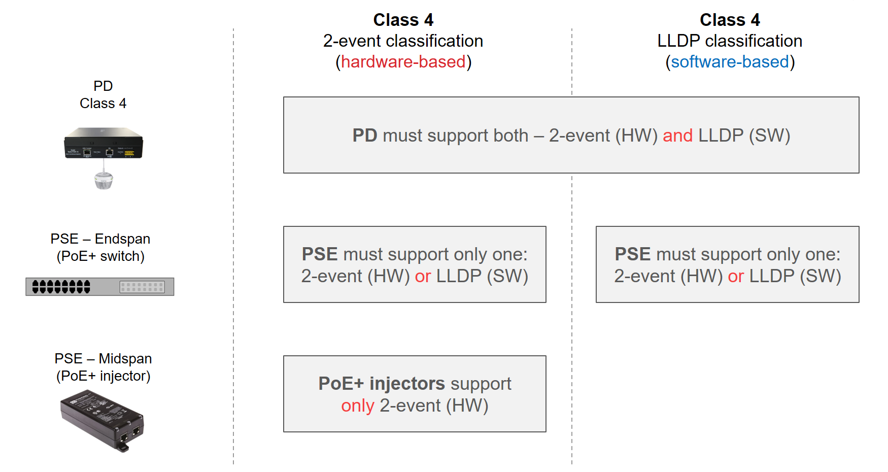
2-event classification support
IEEE 802.3at standard defines that Class 4 PDs must support both hardware-based 2-event classification and software-based LLDP classification, while PSE must only support one of the two, but may support both. PoE+ injectors typically only support hardware-based 2-event classification. Many PoE+ switches support both methods.
Operation
Once the Discovery and Classification stages have completed successfully, the system progresses to Operation mode, where the PD receives sufficient power from PSE and is fully functional.
PoE budget calculation
PoE budget is a specification of multi-port PSE devices (network switches and PoE injectors). This power budget is a shared resource available as needed to all ports. Each PD negotiates power needs with the PSE based on the class of the PD. The PD is then provided with power from the PSE's PoE budget accordingly.
PoE budget may be exceeded during system operation if a PSE is not properly specified. This will cause the PSE to turn off PoE on one and possibly all the ports. The communication with endpoint devices will be interrupted and PoE devices performance could be temporarily or even permanently compromised.
For more information on selecting appropriate PoE switches and calculating PoE power budgets for Tesira devices, please see Specifying PoE switches for Biamp Tesira devices. The same recommendations are applicable for all Biamp PoE-powered devices.
Energy-Efficient Ethernet (EEE)
EEE stands for Energy-Efficient Ethernet (IEEE 802.3az). This standard is intended to reduce power consumption by a PD. However, many of Biamp PDs require constant power provision, especially AVB and Dante devices. These devices will become non-functional if an EEE-capable switch puts its PoE port into a low-power "sleep" state. It is recommended that EEE be disabled for Biamp PDs for guaranteed power provision and device performance.
Cabling
In modern networks, PSEs supply power to PDs over the same standard network cabling that carries the data.
Cat5e or higher category cable is suitable for both IEEE 802.3af and IEEE 802.3at compliant devices.
The maximum recommended length of any Ethernet cable run is 328 ft (100m) from switch to PD, even if a Midspan device is located between the switch and the PD. The Midspan PoE injector should be viewed as a patch panel connection. If the 100m distance is exceeded, power provision and data communication can be negatively affected.
Note that cable type, number of interconnects, integrity of termination and even ambient temperature will affect the electrical resistance presented by the cable path. These factors may reduce the maximum allowable length of the cable.
Data and power pinout
In an Ethernet cable, four twisted pairs are used as the medium for power and data transmission.
For 10/100 Mbit/s Ethernet, IEEE 802.3af/at standards define two powering modes:
- Mode A: voltage is applied between the two data pairs, pins 1–2 and 3–6. Typically used on Endspan PSEs.
- Mode B: voltage is applied between the two spare pairs, pins 4–5 and 7–8. Typically used on Midspan PSEs.
Power must only be applied in one mode at a time, and this decision is made by the PSE. The PSE can support mode A or B or both. Typically, the mode selected is not a concern for an end user because it is a requirement of the IEEE 802.3af/at standards that all PDs must support both modes.
With Mode B, phantom power technique is used to allow the powered pairs to also carry data in 10/100 Mbit/s Ethernet.
Both Modes A and B are supported in Gigabit Ethernet. Phantom power technique is utilized for both modes, as in Gigabit Ethernet all four pairs are used for data transmission.
IEEE 802.3bt "4PPoE" uses all for pairs to provide power in Gigabig Ethernet, hence the name of the standard - 4PPoE ("4-pair Power over Ethernet").
| 10BASE-T / 100BASE-TX (802.3af/at, Mode A) |
10BASE-T / 100BASE-TX (802.3af/at, Mode B) |
1000BASE-T (802.3af/at, Mode A) |
1000BASE-T (802.3af/at, Mode B) |
1000BASE-T (802.3bt) |
||||||
|---|---|---|---|---|---|---|---|---|---|---|
| Pin | Data | Power | Data | Power | Data | Power | Data | Power | Data | Power |
| 1 | Rx + | DC + | Rx + | TxRx A + | DC + | TxRx A + | TxRx A + | DC + | ||
| 2 | Rx – | DC + | Rx – | TxRx A − | DC + | TxRx A − | TxRx A − | DC + | ||
| 3 | Tx + | DC – | Tx + | TxRx B + | DC – | TxRx B + | TxRx B + | DC – | ||
| 4 | Unused | DC + | TxRx C + | TxRx C + | DC + | TxRx C + | DC + | |||
| 5 | Unused | DC + | TxRx C − | TxRx C − | DC + | TxRx C − | DC + | |||
| 6 | Tx – | DC – | Tx – | TxRx B − | DC – | TxRx B − | TxRx B − | DC – | ||
| 7 | Unused | DC – | TxRx D + | TxRx D + | DC – | TxRx D + | DC – | |||
| 8 | Unused | DC – | TxRx D − | TxRx D − | DC – | TxRx D − | DC – | |||