Lenovo TSCIP & TSC Installation, Setup, and Configuration
Biamp UCC-Lenovo TSCIP - MTR Biamp UCC-Lenovo TSC - MTR
Biamp UCC-Lenovo TSCIP - Zoom Biamp UCC- Lenovo TSC - Zoom
Pre-Installation
Important!
Obtain the required setup information beforehand for easier and faster setup once the device is installed.
1. Click one of the links below and download the Teams or Zoom fillable checklist form.
2. Submit the form to your IT department or network owner.
3. The IT department or network owner will provide the following information:
- Device name
- Windows account username and access password
- Teams or Zoom account
Teams Checklist Zoom Checklist

Intended Use and Capability
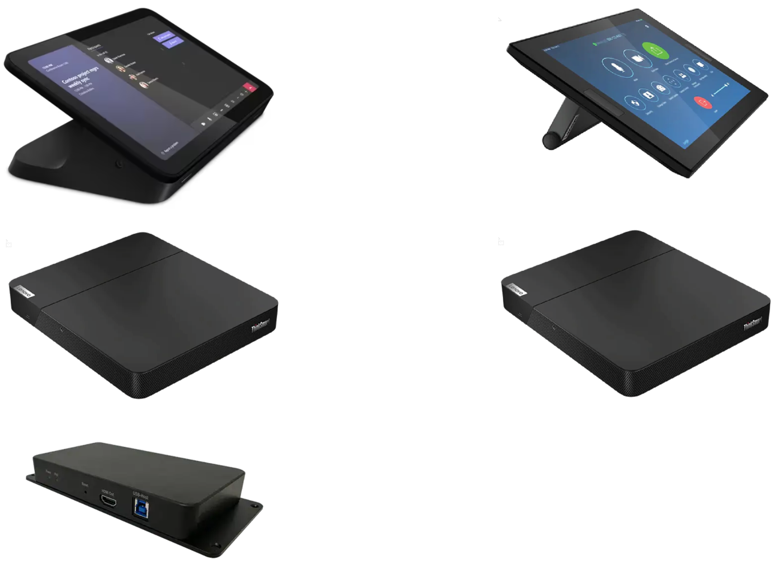
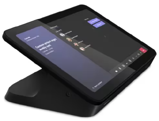
The Biamp UCC-Lenovo TC and TSCIP host Teams or Zoom UC meetings in AV-equipped rooms. They include a TSC or TSCIP Touchscreen Display for system operation with pre-installed UC software. The TSC runs on Windows 10 loT, the TSCIP runs on 11 loT.
Minimum Hardware Requirements
- At least one external display with cable for HDMI-out connection
- Keyboard and mouse
- RJ45 Ethernet cable
- Wired internet connection.
- HDMI cable for HDMI-in connection
Compatible Biamp Devices
ThinkSmart Core and Controller systems integrate AV via USB or IP for the following Biamp products:
- Parle VBC 2500
- Parle ABC 2500
- Parle SBC 2
- Vidi 100/150/250
- TesiraFORTE
- TesiraFORTE X 400/800/1600
- Devio SCR-10/SCR-20/SCR-25
- Devio SCX 400/800
- EX-UBT
- USB200
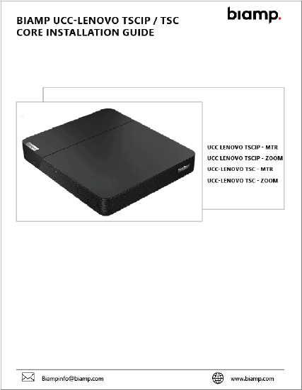
Core Installation Guide
The display touchscreen is designed for placement on flat surfaces like tabletops or desks with the Core computer nearby. Wall-mount and under-table installation options are also available. Click on the link below for instructions.
Click here to download: Core Installation Guide
Connecting IP Devices
See the next section for connecting TSC devices.
Included in the Box
- Core
- Touch Display
- Link Box
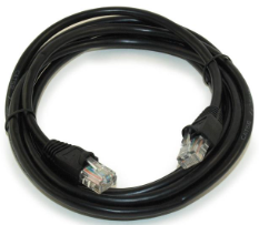
- 5-meter (16.4") CAT5e Cable
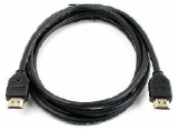
- 2-meter (6.4") HDMI Cable
- 1-meter (3.2") HDMI Cable
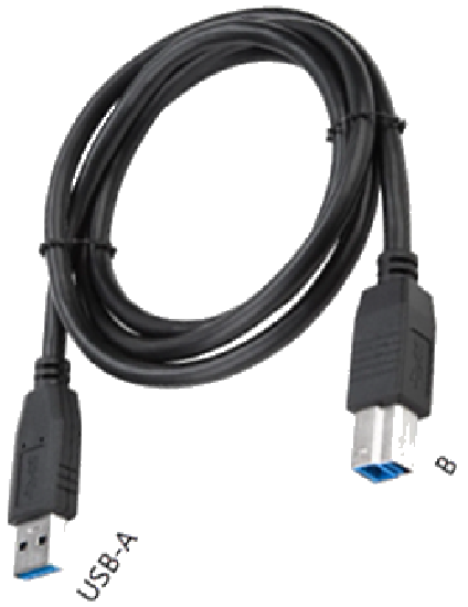
- 1-meter (3.2") USB 3.0 Type-B to USB Type-A Cable
- AC Power Adapter
Once the Core and Display Touchscreen are installed, connect to the room AV devices using the steps below.
Making the connections
1. Check the compatibility and requirements of peripheral devices as well as their connection types.
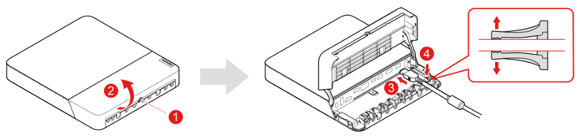
2. Lift the Core cover.
3. Locate the ports on the Core unit.
4. Insert the cables and verify the connections are secure.
5. Go to the next section to set up the Link Box.
>
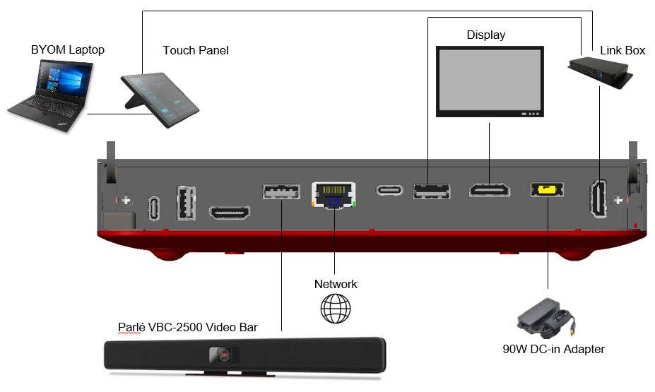
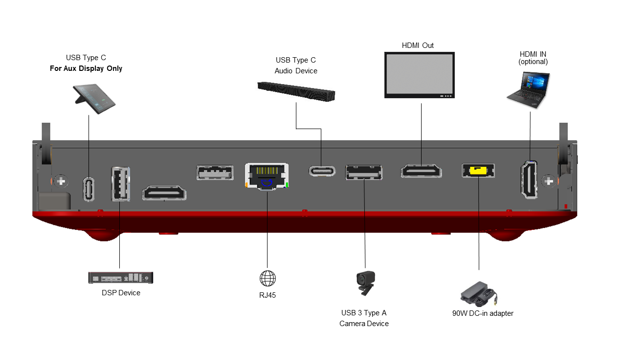
Example Setup
Link Box Setup
Follow the steps below to install the Link Box with the TSCIP system.
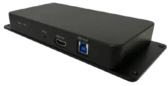
1. Place the Link Box near the host computer (Thinksmart Core). Ensure that the host computer is connected to the internet.
2. Connect the 1-meter (3.2 feet) USB 3.0 Type-B to USB-A cable.
- Type-B side to the Link USB-Host port.
- USB-A side to the host device (ThinkSmart Core) USB-A port.
3. Use the cables to connect the devices to the corresponding ports on the Core. Be sure that the connections are properly inserted and secured.
4. Connect CAT5e cable to the Display (RJ45 port).
5. Connect the 2-meter (6.4-feet) HDMI cable.
- To the Link HDMI Out port.
- To the host device HDMI In port.
6. The Channel ID Switches can be ignored and do not have any function
7. Connect the AC Power adapter
8. A green light on the RJ45 indicates that the Touch Display and Link are connected.
9. Go to the next section for Touch Display Setup.
Touch Display Setup
Follow the steps below to install the Touch Display for the TSCIP.
1. Place the Touch Display on a conference table or any location with easy accessibility.
2. Connect the CAT5e cable to the Ethernet from the Link (RJ45) port.

3. The Channel ID switches can be ignored and do not have any function.
4. If planned, connect the HDMI cable to the HDMI Capture port to a PC system HDMI port.
5. The Touch Display does not require a separate AC Power Adapter. Power is supplied by the CAT5e PoE cable.
6. If the green light on the RJ45 connector is On, the Touch Display and Link are connected.
7. After connecting the Link to a host device, the touch display powers on in about 15 seconds. If the display remains inactive for more than 60 seconds, disconnect and reconnect the CAT5e RJ-45 cable. This is only required during the initial installation.
Important! Once the connections are secure, go to the Software Deployment Procedure section.
Connecting TSC Devices
See the previous section for connecting IP devices.
Included in the Box
- Core
- Touch Display
- AC Power Cord
Once the Core and Display Touchscreen are installed, connect to the room AV devices using the steps below (refer to diagrams).
Making the connections
1. Check the compatibility and requirements of peripheral devices as well as their connection types.
2. Lift the Core cover.
3. Locate the ports on the Core unit.
4. Insert the cables and verify the connections are secure.
Important! Once the connections are secure, go to the Software Deployment Procedure section.
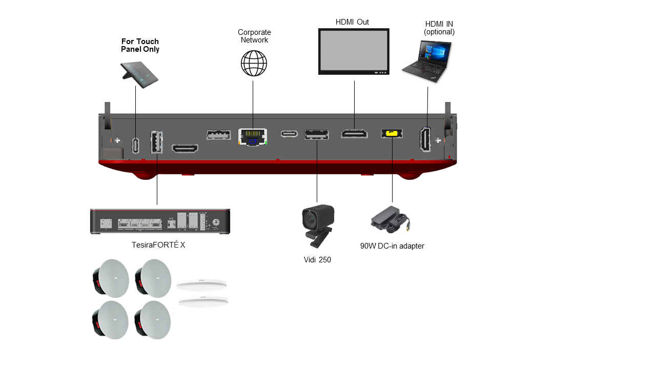
Huddle and Small Room Example Setup
Medium and Large Room Example Setup
Software Deployment Procedure
Important! This section is required for all TSCIP and TSC systems.
Have the completed IT or network owner's checklist handy to enter the required information during software deployment.
1. Connect a keyboard and a mouse to the Core for easier setup instead of using the touchscreen user interface.
2. Turn on the Core to display the login screen.
- Ensure the Core maintains a stable connection as the system may require firmware updates.
4. Use the Microsoft Windows credentials provided to set up the Core's login credentials.
5. Follow the on-screen instructions to set up and configure the Windows account.
- The Lenovo Manager setup is optional and can be skipped for now.
- Once Windows is set up, the Core will prompt you to choose between Teams and Zoom.
- For Teams, change the default administrator password to the one provided on the checklist.
- Follow the on-screen setup instructions using the information from the checklist.
- For Zoom, sign into the application using the code provided in the checklist.
6. Once the accounts are set up, ensure that the Core recognizes the peripheral devices in the Settings menu.
7. Test to verify the proper functioning of Teams or Zoom by joining a test meeting, testing audio and video functionality, and verifying network connectivity.
Reset Lenovo Warranty Period
Align the warranty to the date of purchase from Biamp here.