Enabling AVB on Control4 Pakedge S3 switches
Note: Pakedge AVB switches have been discontinued and are no longer available for purchase.
This article describes how to enable AVB on the Control4 Pakedge S3L-24P / S3-24P switch. AVB must be enabled for any Tesira system that utilizes AVB. It is important to note that the Control4 Pakedge S3L-24P/S3-24P switches are Avnu certified and AVB is enabled as part of the switch firmware. These switches also offer a 380W PoE+ power budget that can be applied across 24 ports.
Contact support@pakedge.com for:
- Current firmware
- Switch/network capabilities
- Expectations regarding simultaneous support of AVB, Dante and AV-over-IP solutions (NVX, SVSI, etc.).
- Product availability
Switches should have S3L_runtime_1.0.B8.img loaded to both firmware images.
Login to the switch
The Pakedge switch S3L-24P / S3-24P can be configured via web browser by entering the IP address. By default, VLAN1 is assigned to ports 1-28 so your computer will need to be connected to one of these ports. The Default IP address and credentials are as follows:
192.168.1.205
Username: pakedge
Password: pakedges
Once you are logged into the switch, there are 2 options to Enable AVB traffic. We'll cover each option in detail below:
Option 1 - Manually Enable AVB
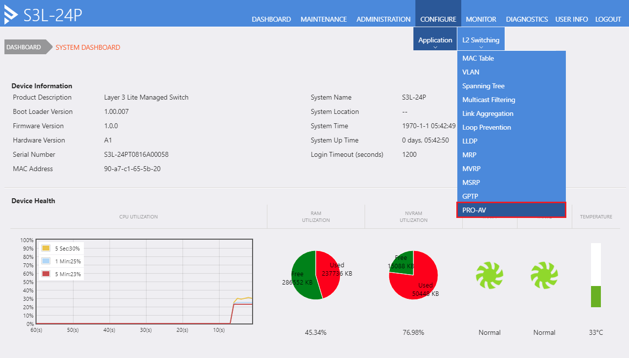
1. From the drop-down tool bar, select CONFIGURE -> PRO-AV
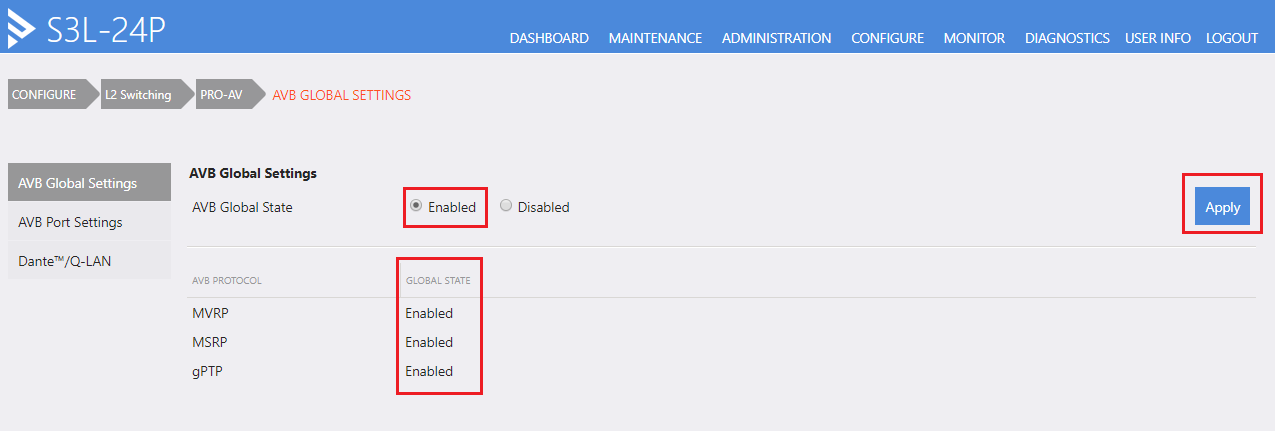
2. Click “Enable” under AVB Global State, and hit “Apply”, the state of AVB PROTOCOL MVRP, MSRP and gPTP will change from Disabled to Enabled.
3. In the “AVB Port Settings”, select the “Port” drop down manual (in the example: eth1/1 – eth1/12), which will enable port 1 - 12 for running AVB, and hit “Apply”, after applied, the MVRP, MSRP and GPTP column on port 1 - 12 will change to “Enabled”
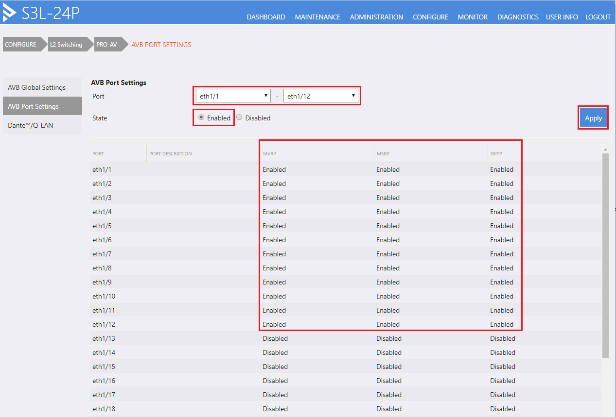
*Notice that AVB can be enabled on a per-port basis as needed for the project. If AVB is enabled on a port that has a non-AVB capable device connected, the switch will report AVB related failure messages on this port. This is expected as the connected device is not AVB capable.
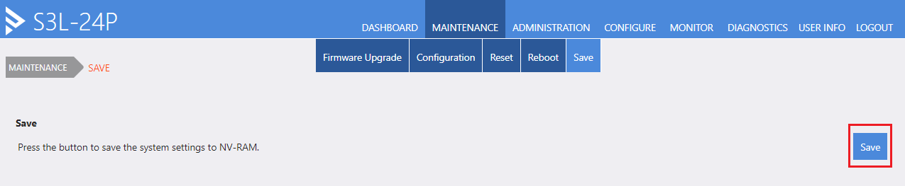
4. The last step is make sure the configuration is saved under the following drop-down menus: MAINTENANCE -> Save in the tool bar, and hit the “Save” button on the right-hand side to save the configuration into the NV-RAM.
*Notice that, if AVB and Dante/Q-LAN are to be used on the switch at the same time, AVB must be enabled first. AVB and Dante/Q-LAN can exist on the same switch, but they cannot share a single port due to PTP variations. This becomes an important detail when sharing AVB and Dante/Q-LAN across multiple switches as it may require dedicated uplinks/trunks for each respective protocol type.
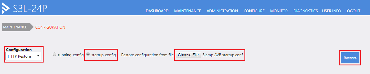
Option 2 - Upload the startup config file with AVB enabled
Go to MAINTENANCE -> Configuration, select “HTTP Restore” from the Configuration drop down menu, select “startup-config”, click “Choose File” and select the startup configuration file from your computer, and click “Restore”
The switch must be rebooted for the configuration to load: go to MAINTENANCE -> Reboot to reboot the switch.
An example configuration file with AVB enabled on ports 1 – 12 can be downloaded here.
Reset the switch to factory defaults
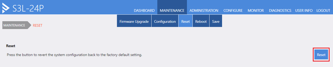
If a user is uncertain of the switch configuration, it is often recommended to reset the switch to factory defaults. Reset to factory defaults can be achieved by pressing the 'Reset' button on the front of the physical switch or via the GUI:
Press and hold the “RESET” button on the front of the switch for 5 seconds.
Under the web browser, go to MAINTENANCE -> Reset in the tool bar, and hit the “Reset” button on the right-hand side.
After performing a factory reset you will need to enable AVB again.
AVB isn't working
If AVB is not working or endpoints are failing discovery there are some basic things to check first:
- Switches should have S3L_runtime_1.0.B8.img loaded to both firmware images. Earlier firmware versions will not properly support Tesira expanders.
- Verify AVB is enabled on all connected ports with AVB endpoints. Save settings.
- Verify AVB is enabled on all uplinks between switches, and on all mid-span switches. The AVB path must be enabled across the entire route between devices. Save settings.
- Save settings and reboot each switch after making configuration changes. Double check the settings to ensure they loaded as expected.
- Verify the expected AVB ports are all participating in VLAN 2. Verify VLAN 2 has not been manually configured for any purpose, including AVB. The switch automatically (dynamically) assigns VLAN 2 for AVB traffic. This is all handled 'under the hood' using rules implemented by the switch software.
- If a VLAN is desired for control or other traffic it is vital that VLAN 2 is not used. AVB traffic should be allowed to be dynamically assigned to VLAN 2 by the switch, and should not be manually assigned to another VLAN.
- Configure > L2 switching > GPTP:
- gPTP Current will show the "steps removed" from gPTP source. If this is 0 then this switch is providing gPTP grandmaster (GM). GM Clock Identity is the MAC of the GM source (there will be a :FF:FE in the middle of the MAC address).
- gPTP Parent will also identify the clock grandmaster (GM) device. Note that the "parent port number" is the egress port of the next upstream gPTP device, not the local ingress port.
Further reading
The Control4/Pakedge S3 series switches are available for purchase through certified Control4/Pakedge partners and for that reason, the Pakedge Knowledgebase is restricted to certified partners. Select knowledgebase articles have been provided; however, if additional support is needed, please contact Biamp support, Pakedge support or your certified Pakedge dealer.
- Enabling AVB and Dante on the Pakedge S3-Series switches.
- Creating VLANs on the Pakedge S3-Series switches.
- Creating IP Interfaces on Pakedge S3-Series switches.
- Configuring DHCP Server on Pakedge S3-Series switches.
- Configuring IGMP on the Pakedge S3-Series switches.
- Configuring Port Mirroring on the Pakedge S3-Series switches.
- Pakedge - How To - Enable AVB.mp4
- Pakedge - How To - Set Secondary IP on a VLAN.mp4
- Pakedge - How To - Set Switch IP on a VLAN.mp4