L-Acoustics AVB
This article describes using the L-Acoustics LS10 AVB network switch with Tesira AVB devices, along with Network Manager, the P1 processor, several AVB-capable amplified controllers, and the Hive AVDECC Controller.
L-Acoustics products including the LS10 switch are Avnu-certified AVB devices.
 Hive AVDECC controller
Hive AVDECC controller software can be used (but it is not always required) to monitor and route AVB endpoints between Tesira and L-Acoustics devices. The L-Acoustics devices have integrated AVDECC capabilities which allows stream routing directly within the L-Acoustics Network Manager software.
Tesira devices will only appear in Hive if they have AVB IO blocks (explicit AVB) in their layout. Tesira which only uses implicit AVB (automatically routed between devices in the system compilation process) will not appear in the Hive AVDECC controller.
L-Acoustics Network Manager software
L-Acoustics Network Manager (LA NWM) software is used for discovery, configuration, and communication with the LS10 and other L-Acoustics hardware.
LA NWM version 2.5 and later includes an AVB controller implementing the IEEE 1722.1 standard (also known as AVDECC).
LS10 switch
The LS10 is an Avnu-certified, 10-port AVB enabled switch which ships pre-configured for AVB, and it can support the management of up to 150 AVB streams regardless of the channel count within each stream. The switch has (8) 1Gb EtherCON RJ-45 ports and (2) SFP cages which support 1Gb RG45 copper or 1Gb fiber transceivers.
The LS10 has a 5-second boot up time, reflecting L-Acoustics sensitivity to the effect of system down time during any performance.
The LS10 runs on 100VAC-240VAC 50Hz-60Hz with 24VDC redundancy available. It also has a 6-pin GPIO connection which allows for 24VDC output to supply backup power to another switch, 24VDC input for backup power, and a contact closure which indicates alarms in the device. Alarms which will trigger the GPIO are selectable in software.
L-Acoustics recommends ensuring the switch firmware is at the latest release before putting the switch into use.
Switch management via LA NWM
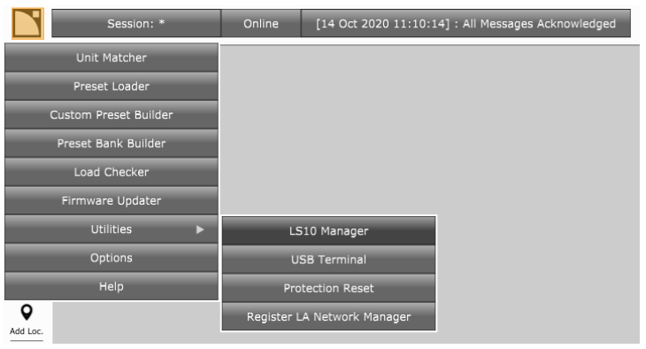
After launching LA NWM software open the LS10 Manager found in the Utilities section of the main menu (click on the L-Acoustics logo).
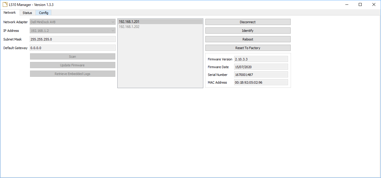
Network tab
The LS10 switch ships with a default static IP address of 192.168.1.200, the control PC must be in the same IP range for discovery. (Switch management can also be done via a micro USB connection on the rear panel.)
Select your desired network adapter then choose Scan to find any LS10 on the network, then Connect to open a management session with a switch.
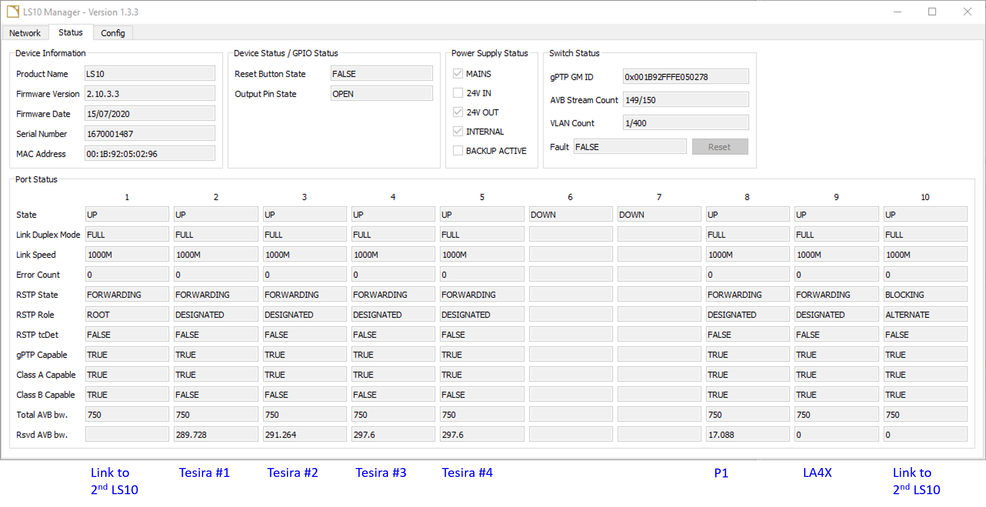
Status tab
The status tab includes:
- switch device information including FW and MAC address
- GPIO state
- power supply status
- gPTP GM ID (showing the AVB network Grandmaster device, on an AVB network this will be a switch not an AVB endpoint)
- AVB stream count (number of AVB talker streams on network)
- VLAN count
- general fault state
Port status shows:
- port state, mode, and speed
- error count
- RSTP: state (forwarding or blocking), role (root, alternate, or designated), and tcDet (topology change detected true or false)
- gPTP capable (is this port connected to an AVB capable device?)
- Class A and B (does the connected AVB device support Class A AVB, Class B AVB, or both?)
- Total AVB bandwidth available (typically defaults to 75% of the port capacity)
- Reserved AVB bandwidth (how much AVB bandwidth is currently reserved by talker streams sourced from this port?)
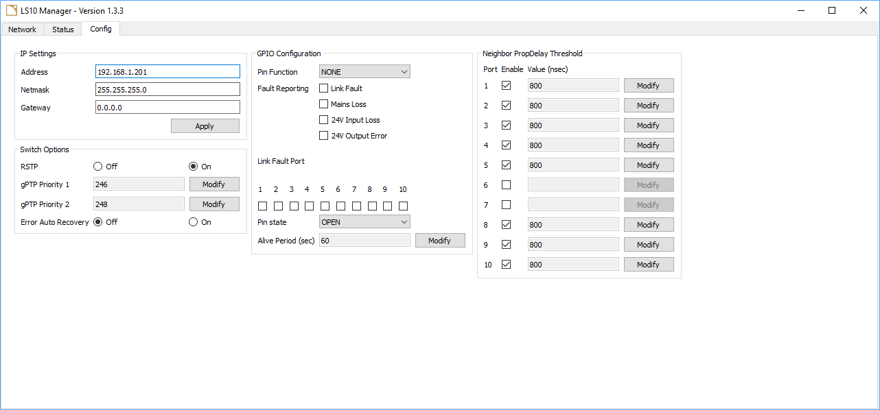
Config tab
There are some user configuration options in the LS10, including:
- management IP address
- RSTP enable/disable (enabled by default)
- gPTP priority ranking (LS10 is capable of acting as gPTP grand master)
- error auto-recovery, used in case of optical link disconnection in redundant network topologies
- configuration for fault reporting via GPIO
- propagation delay threshold
P1 AVB processor – Measurement platform
The L-Acoustics P1 AVB processor is an Avnu-certified 20 in x 16 out measurement platform with 8x8 matrix routing for analog, AES/EBU, and AVB signals. P1 allows bridging of AVB, AES/EBU and analog audio with time-aligned redundant signal distribution. The P1 combines the functions of an EQ station with delay and dynamics processing and a multi-mic acoustic measurement platform with offline delay finder and EQ modelization.
(2) AVB streams of up to 8 channels can be received by the P1 and (2) AVB streams of up to 8 channels can be transmitted by the P1
The P1 allows creation of redundant AVB networks for supported L-Acoustics amplifiers. L-Acoustics AVB network redundancy is not compatible with Tesira Server/Server-IO AVB-1 card network redundancy.
AVB clock hierarchy
When using 3rd party AVB hardware with Tesira attention must be paid to the AVB clock hierarchy to ensure all AVB endpoints are in sync.
Tesira AVB can be clocked to one of 2 sources:
- internally (a configured Tesira system elects its own AVB master clock device which provides an AVB pilot stream to all other Tesira devices in the system to maintain clock sync. A system may also contain Dante or CobraNet I/O cards and the designer may elect to use one of those media formats for the system master clock. If another media format is selected for media master clock then Tesira AVB clocks will be slaved to the other media type and any 3rd party AVB devices must be slaved to the Tesira AVB clock. In this scenario, failure to slave 3rd party AVB to the Tesira AVB clock will ultimately cause clock drift which will result in loss of audio.) (P1 should be set to "slaved to the clock of AVB Audio Input Stream")
- slaved to the clock of an AVB audio input stream (if Tesira is slaved to an external clock source via an AVB input stream then the Tesira DSP device hosting that AVB input block is elected the Tesira system's media master clock device. If the Tesira system also contains Dante or CobraNet interfaces they will inherit clock from the AVB media domain. In this scenario Tesira must be the master clock device for any connected Dante or CobraNet media networks.) (P1 should be clocked internally and Tesira's AVB clock must be slaved to the P1 output stream using an AVDECC controller software.)
The P1 can be clocked to one of 4 sources:
- internally
- slaved to an AVB media clock stream
- slaved to the clock of AVB Audio Input Stream 1
- slaved to the clock of AVB Audio Input Stream 2
For more detail on Tesira with multiple digital media interfaces refer to Using multiple networked audio protocols with Tesira.
Audio from Tesira to P1
When connecting a Tesira output to L-Acoustics devices, an 8 channel AVB output block should be added in Tesira (the block should be set as fixed in unit = true). In systems with multiple Tesira devices it can be helpful to add the last 6 characters of the Tesira AVB Primary MAC address to the stream name (e.g. - "P1-to-Tesira-15C12F" or "Tesira-13F2B0-to-P1") for device identification in Hive.
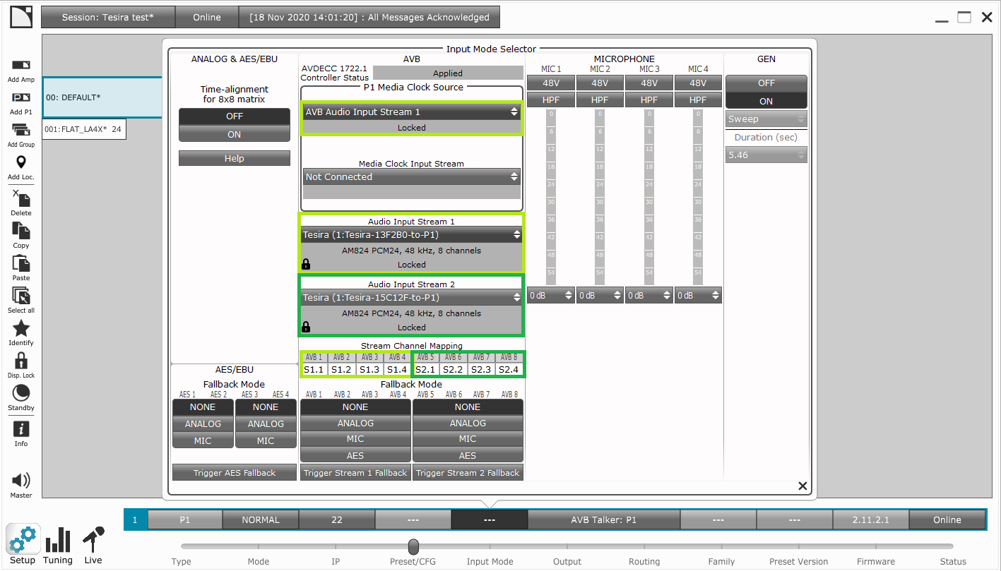
The P1 Media Clock Source can be set to automatically follow the clock of AVB Audio Input Stream 1. This will slave the P1's clock to Tesira's clock. If Tesira is to be slaved to the P1's clock see Slaving Tesira to an AVB stream clock from P1 using Hive.
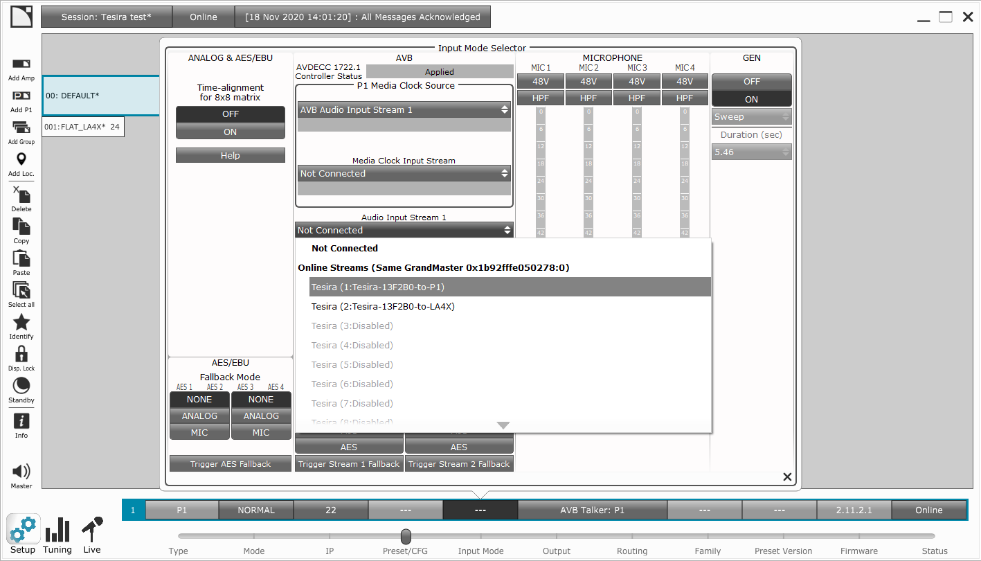
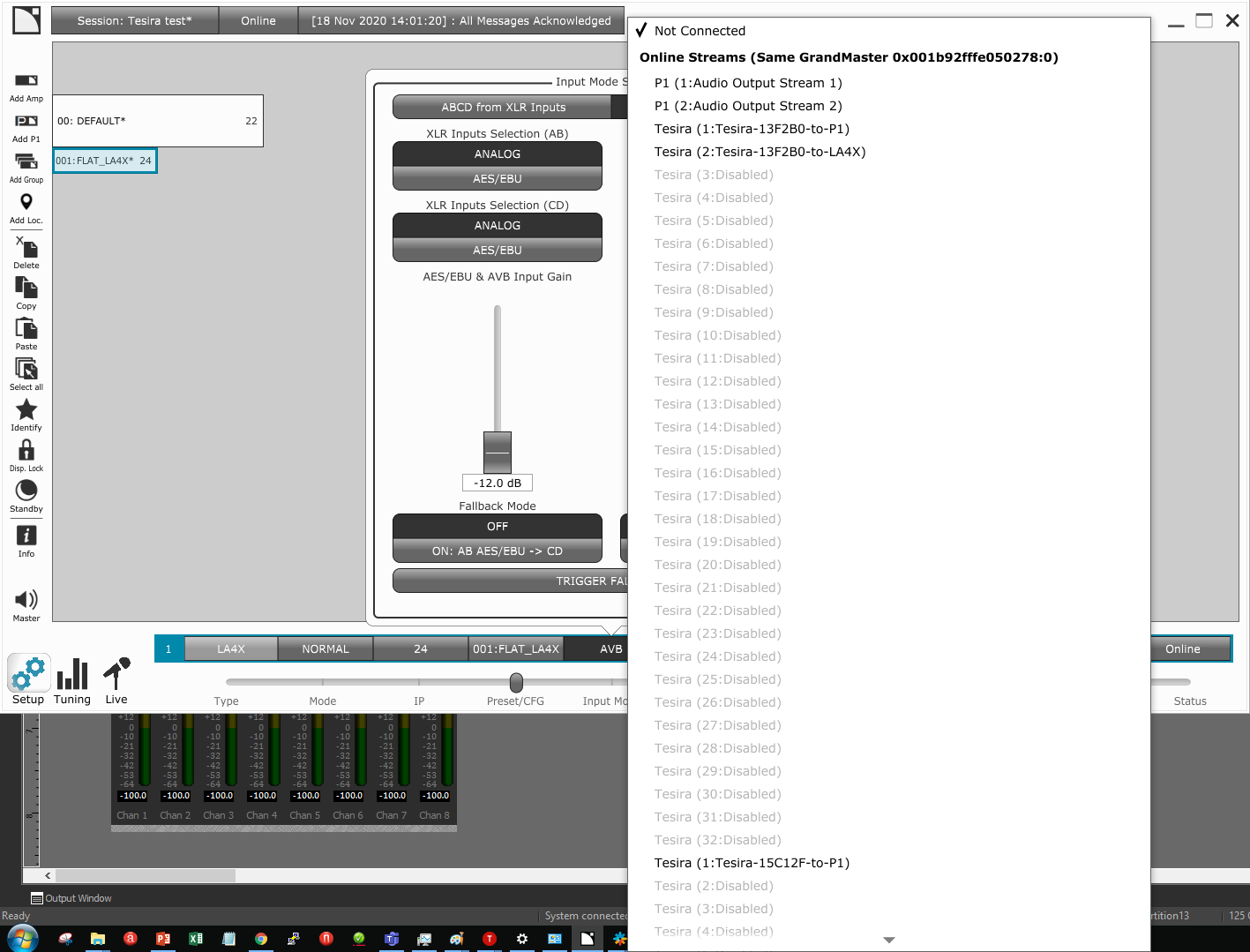
The desired Tesira stream can be connected directly in Network Manager in the P1's Input Mode window. The connected stream format is shown in the Audio Input Stream drop menu. L-Acoustics controllers and Tesira AVB stream formats will only match for AM824 PCM24, 48 kHz, 8 channels. The P1 will only allow connection to matching stream formats using the drop menu.
Each Tesira will present 32 streams in the drop menu. Those associated with an IO block will be shown in black with a stream name, those which are not associated with an IO block will show Disabled in grey text. With multiple Tesira talkers it may be necessary to scroll down to find the desired active stream.
2 different AVB input streams can be connected to P1 and channels routed using the Stream Channel Mapping properties. This is helpful if multiple mixing consoles are connected to P1 but may be less common when sourcing content from Tesira. P1 allows a total of 8 active input channels from AVB.
If 2 AVB input streams are sourced from 2 unique Tesira systems then it is vital that the hierarchy of device network clocks is properly planned and managed.
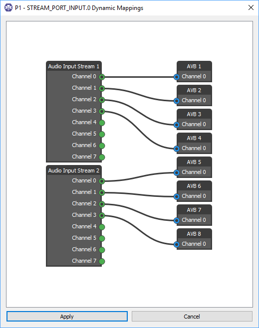
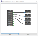
When the P1 is used to receive audio from Tesira the stream may initially be connected with only channels 1 and 2 routed. In the Stream Channel Mapping the AVB input channels are labeled AVB1, AVB2, ..., AVB8. Any unassigned channels will show anX, while connected channels will be populated in the formatS1.1 for input stream 1, channel 1. To edit or add input channel assignments click in the field below each channel name to manually enter a source stream, period, channel number. (e.g. - use the format 1.3 for input stream 1, channel 3)
Input Channel Mapping can also be done by right clicking on a Listener device name in Hive controller and choosing 'Edit Dynamic Mappings...' then wiring as desired.
Audio from P1 to Tesira
When connecting an L-Acoustics P1 output to Tesira devices an 8-channel AVB input block should be added in Tesira (the block should be set as fixed in unit = true).
In systems with multiple Tesira devices it can be helpful to add the last 6 characters of the Tesira AVB Primary MAC address to the stream name (e.g. - "P1-to-Tesira-15C12F" or "Tesira-13F2B0-to-P1") for device identification in Hive.
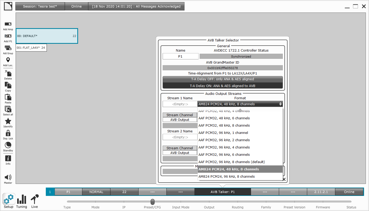
L-Acoustics and Tesira AVB stream formats will only match when AM824 PCM24, 48 kHz, 8 channels is selected in the P1's AVB Talker Selector: Audio Output Streams drop menu.
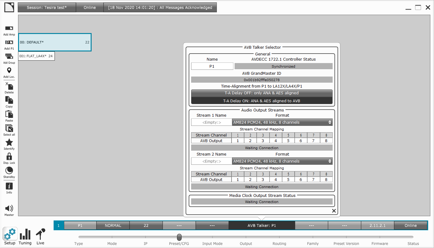
Output Channel Mapping can also be done by right clicking on a Talker device name in Hive controller and choosing 'Edit Dynamic Mappings...' then wiring as desired.

Slaving P1 to Tesira's AVB media clock
If P1 is to be slaved to Tesira's AVB media clock then an 8-channel AVB output should be added to Tesira and routed to P1 for this purpose (the block should be set as fixed in unit = true). This Tesira stream may either be selected as the Media Clock for P1, or the stream can be selected as an AVB audio input stream and followed as clock source. Refer to the section on AVB Clock Hierarchy when multiple media formats are in use in Tesira.
Slaving Tesira to an AVB stream clock from P1 using Hive
If the P1 is to provide master clock then the Tesira system AVB needs to be manually slaved to the P1 AVB. This is done by slaving the Tesira AVB listener to the P1 talker using Hive or another AVDECC controller. (Whether the P1 is the AVB master or if the P1 is slaved to another AVB master source, such as a mixing console, Tesira must still be manually slaved to the P1 to properly sync the clocks.)
Tesira will be slaved to the P1 AVB clock using an AVB input stream. In Tesira software determine which Tesira device is hosting the AVB receive block from the P1 (the block should be set as fixed in unit = true). In the Tesira Equipment Table note the MAC address for the AVB port on that unit.
In systems with multiple Tesira devices it can be helpful to add the last 6 characters of the Tesira AVB Primary MAC address to the stream name (e.g. - "P1-to-Tesira-15C12F" or "Tesira-13F2B0-to-P1") for device identification in Hive.
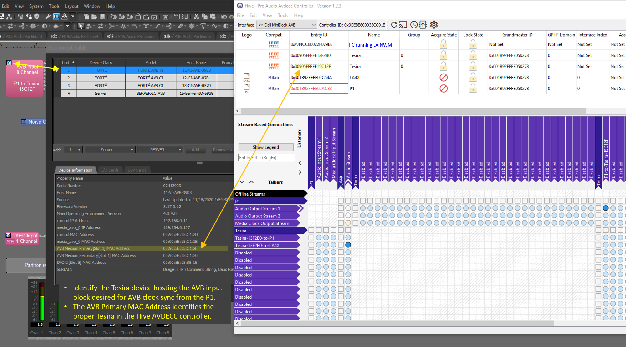
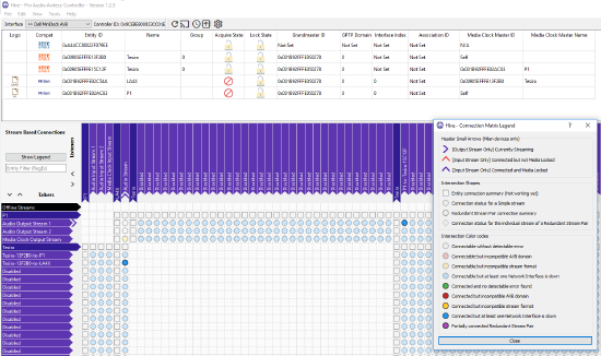
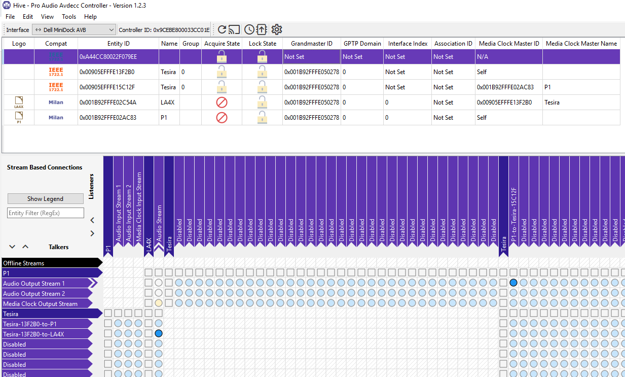
Tesira devices in Hive cannot be named individually but are listed by their AVB Primary MAC address.
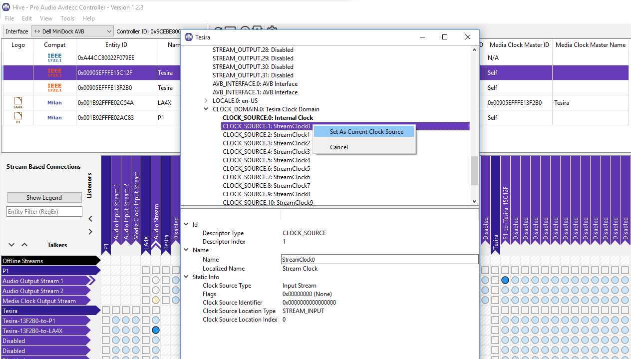
In the Hive View menu, verify Entity Model Inspector is checked, this pane can be pinned or floating. Highlight the Tesira unit from the Equipment Table. The Tesira's AVB attributes will be shown. Verify the presence of the expected AVB input stream and note the stream number (e.g.- STREAM_INPUT.0: P1-to-Tesira-15C12F).
Scroll down and expand the section CLOCK_DOMAIN.0: Tesira Clock Domain.
Right click on the desired clock source stream then chose Set as Current Clock Source. (e.g - When the first audio stream has been selected as the clock source CLOCK_SOURCE.1:StreamClock0 should appear in bold.)
The P1 should be indicated as the Media Clock Master in the Hive primary screen. If L-Acoustics amplified controllers receiving their AVB streams from Tesira they will show the connected Tesira as their clock source.
In the system below a P1 provides clock and audio to a Tesira system (2 devices shown) which distributes clock and audio to an LA4X.
LA4X, LA2Xi, LA12X amplified controllers
Three models of L-Acoustics amplified controllers currently support AVB and accept AM824 PCM24, 48 kHz, 8 channel media streams.
- The LA2Xi is a 4-input x 4-output amplified controller which delivers 4 x 640 W RMS power at 4 Ω. Designed to match the power of small format loudspeakers, LA2Xi can also be used to support larger loudspeakers at lower SPL capability (4 x 4 single-ended mode) or at full SPL capability (4 x 3, 4 x 2 or 4 x 1 bridge mode). LA2Xi supports analog, AES/EBU, and AVB inputs.
- The LA4X is an Avnu-certified 4-input x 4-output, 1,000W per channel amplified controller with integrated DSP for signal processing. LA4X supports analog, AES/EBU, and AVB inputs.
- Only LA4X amplified controllers with HARDWARE INFO ID4 or higher (in MONITORING & INFO menu) support AVB (but do not support redundancy)
- The LA12X is an Avnu-certified 4-input x 4-output, 12,000W amplified controller with integrated DSP for signal processing. LA12X supports analog, AES/EBU, and AVB inputs.
Connecting to Tesira
 One AVB stream of up to eight channels may be connected to the amplified controller and up to four channels can be retrieved from this stream. Channel routing is done by manually typing the stream channel number into the correct field in the Stream Channel Mapping, or by right clicking on a Listener device name in Hive controller and choosing 'Edit Dynamic Mappings...' then wiring as desired.
L-Acoustics amplified controllers automatically sync their AVB clocks with the device providing their selected AVB audio input stream.
When connecting an L-Acoustics device to Tesira an 8-channel AVB block should be added in Tesira (the block should be set as fixed in unit = true).
In systems with multiple Tesira devices it can be helpful to add the last 6 characters of the Tesira AVB Primary MAC address to the stream name (e.g. - "P1-to-Tesira-15C12F" or "Tesira-13F2B0-to-P1") for device identification in Hive.
The desired Tesira stream can be connected directly in Network Manager in the amplified controller's Input Mode window. The connected stream format is shown in the Audio Input Stream drop menu. L-Acoustics amplified controllers and Tesira AVB stream formats will only match for AM824 PCM24, 48 kHz, 8 channels. The amplified controllers will only allow connection to matching streams using the drop menu.

General AVB information from LA NWM help file
- VLAN ID 2 is used by default by AVB bridges and talkers.
- It is recommended not to exceed the following number of hops in any network path between talkers and listeners:
- 100 Mb/s networks: 7 hops
- 1 Gb/s networks: 13 hops
- Number of hops = number of AVB bridges in the path + 1
- LA4X, LA12X and LA2Xi amplified controllers, and P1 processors can participate to an AVB network, and receive and send digital audio signals through AVB streams using the same network architecture as the one used for real-time monitoring and control of the physical Units.
- All L-Acoustics AVB-capable units embed an AVB bridge that is able to forward up to 150 streams..
- For audio, a stream can contain 1 or more audio channels. A single AVB stream can be received by several listeners. The talker uses multicasting to transmit the audio content only one time and the AVB bridges replicate the data to all connected listeners. There are two classes of streams: class A streams have a 2 ms network latency, class B streams have a 50 ms network latency (default values). L-Acoustics AVB-capable units are compatible with streams in the AAF PCM32 format at 96 kHz containing from 1 to 8 channels. DSP mapping allows selecting which channel(s) to use from the stream.
- At a given time, an AVB device is part of one, and only one, AVB domain. A stream transmitted by a talker can reach any listener of the same domain, but is blocked at the boundaries of this domain. A boundary is created when an AVB bridge is connected to a non-AVB device (or to an AVB bridge with a different bridge configuration).
- The talker timestamps the AVB samples using the network clock absolute reference (with sub-µs accuracy), adding 2 ms for class A stream. This allows taking into account the latency of each network path. Each listener buffers the audio according to its specific network path latency to ensure synchronous rendering.
- Wi-Fi does not support class A AVB streaming and most Wi-Fi access points do not allow AVB control.
- Set up all physical connections and turn on all devices before starting operations.
- Do not connect a non-Avnu certified device to an already up and running network as it can disrupt connections (for example by imposing a new gPTP grandmaster).
- Refer to the documentation of all third-party AVB-capable devices before connecting them to the units - some devices are designed for small-scale networks or specific types of product.
- Re-establishing connection through RSTP can take several seconds, depending on the size and complexity of the network, and the capabilities of connected devices.