Connecting a Shure MX400DP to an EX-LOGIC
One popular application for the EX-LOGIC is to interface with conferencing microphones that feature mute switches and LED indicators, and Shure is a leading manufacturer of such microphones. This article describes how to physically connect a Shure MX400DP microphone desktop base to a Tesira EX-LOGIC.
Note that even though this article shows diagrams for only the EX-LOGIC, the logic I/O terminals that are built into Tesira servers and TesiraFORTÉs can be used for the same purposes as an EX-LOGIC.
Goal
After completing the steps in this article, you will be able to connect a Shure MX400DP to a Tesira EX-LOGIC. This will allow your Tesira configuration to control the LED's on the MX400DP, and it will also allow the mic's mute switch to control functions within your Tesira configuration (like mic muting).
Note that Shure MX series microphones use phantom power to power its LED's. Therefore, no external power supply is required for this application.
Conductor colors
The Shure MX400DP is a desktop mic base that is designed to work with Shure MX405, MX410, and MX415 gooseneck microphones, each of which has either a single-color LED ring or a bi-color LED ring, depending on the model. The MX400DP comes with a cable that is pre-terminated to a 3-pin XLR, with 2 additional logic conductors available inside the XLR connector housing. The conductor color code for this cable is as follows:
| Conductor Color | Function |
|---|---|
| Red | Audio + |
| Black | Audio - |
| Green | Audio/Logic Ground |
| Orange | LED In |
| White | Switch contact |
Wiring
The audio conductors on the microphone will connect to the audio inputs on the Tesira device like a typical microphone. The LED and switch conductors will connect to the EX-LOGIC. The LED In (orange) conductor connects to a logic output, and the Switch Contact (white) connects to a logic input.
Note that Shure MX series microphones use phantom power to power its LED's. Use the Logic Output block in the Tesira configuration (not the LED Driver).
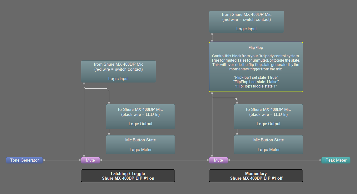
Each MX400DP uses two I/O terminals on the EX-LOGIC, meaning that a maximum of 8 MX400DP's can be connected to a single EX-LOGIC. The diagram below shows a typical wiring scheme for a single MX400DP:

DIP switches
DIP switch 3 should always be in the UP position to ensure that the mic is not locally muted when the mute switch is pressed.
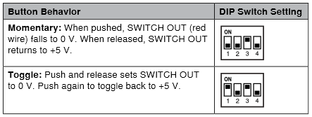
If DIP switch 1 is in the UP position, the mute switch will behave like a toggle switch. If DIP switch 1 is in the DOWN position, the mute switch will behave like a momentary switch.
LED control
Shure MX405, MX410, and MX415 gooseneck microphones have a bi-color LED ring. This LED ring will light up green when there is less than 1V across the orange and green conductors (i.e., logic output in the low state), and it will light up red when there is 5V across the orange and green conductors (i.e., logic output in the high state).
Shure MX405R, MX410R, and MX415R gooseneck microphones have a single-color LED ring. This LED ring will light up when there is less than 1V across the orange and green conductors (i.e., logic output in the low state), and it will turn off when there is 5V across the orange and green conductors (i.e., logic output in the high state).
Further reading
- Once the device is physically connected to the EX-LOGIC, you'll need to program it. See EX-LOGIC programming for more information.
- Muting microphones with logic