Wiring switches to Tesira GPIO or the EX-LOGIC
Of the many options that can be used to control Tesira, one option is to use external switches and pushbuttons to initiate actions. Since switches are analog devices, these need to be connected to Tesira through onboard GPIO or using EX-Logic. This article covers the details on wiring off-the-shelf switches, Biamp’s RP-S4 Remote Panel, as well as sensors to the EX-Logic or onboard GPIO.
Wiring a generic switch
Wiring generic, off-the-shelf switches to the EX-Logic is very straightforward. Each switch should be wired between the ground terminal and the proper logic pin as indicated in the diagram below. Any ground terminal in the EX-Logic can be used for the ground connection.
Wiring the RP-S4
The Biamp RP-S4 is a wall plate with four double-pole/double-throw (DPDT) switches. These switches are prewired from the factory with the poles tied together so it works as a single-pole/double-throw (SPDT). Each switch has three wires: white, red and green. The red wire is common while white and green are the contact wires. When the switch is pressed, a short will be present between the red and green wires. Releasing the switch will break that connection and short the red and white wires. For most applications, only the red and green wires need to be connected to the ground terminal and the logic input terminal of the EX-Logic respectively as shown below.
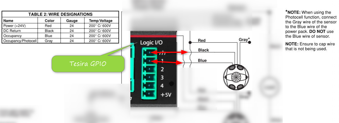
Utilizing a Motion/Occupancy Sensor
Some motion/occupancy sensors offer low voltage output triggers that can be used by Tesira to recall presets. Note the emphasis on low voltage as Tesira GPIO is not rated for high voltage. The example utilizes a Leviton OSC20-M0W which provides 0V or 24V output based upon motion detection. The wiring is as follows:
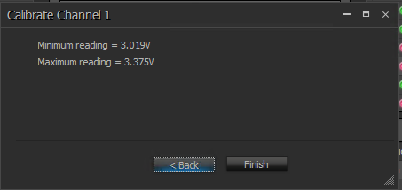
The Tesira GPIO - Control Voltage input will need to be calibrated to sense the minimum and maximum voltage presented by the occupancy sensor. The internal GPIO Voltage Control circuitry is used to working with ranges of 0-5V so it shunts the occupancy sensor voltage range to the following range when calibrated:
Now it is time to add a Control Voltage block to the Tesira system file and have it control a level control.
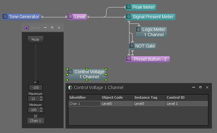
A Signal Present Meter is configured for the desired level threshold and debounce delay resulting in the following low/high results:
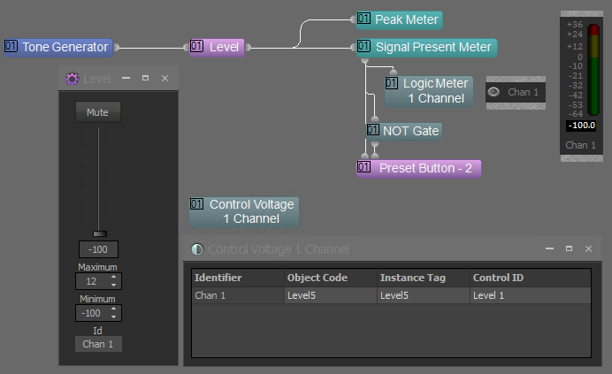
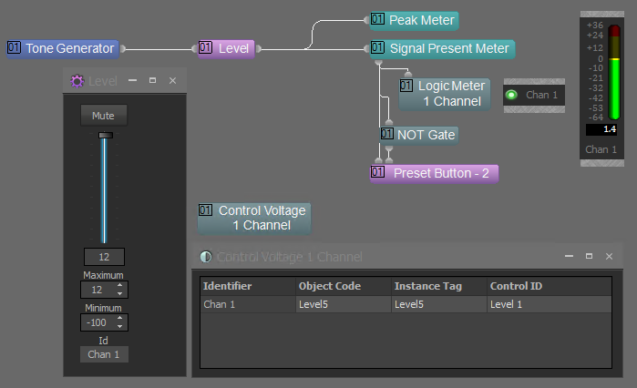
The Preset Button block then allows recall of presets as needed.
- It is worth noting that the ultrasonic sensors have been disabled in the OSC20-M0W as such frequencies can be sensed by Parle microphones.