Parlé Presenter Lift: System Commissioning
This article covers the final phase of a Parlé Presenter Lift (PPL) deployment: configuring the processing blocks and tuning the system for optimal gain-before-feedback. This hands-on process requires careful, methodical adjustments. Every step in this tuning process is essential in achieving the goal of 6-12 dBA system gain.
Hardware and requirements
Applicable hardware
This article applies to the following Biamp hardware and software:
- Microphones: Parlé TCM-X, Parlé TCM-XA, Parlé TTM-X
- PoE Amps: AMP-450P, AMP-450BP
- Processors: TesiraFORTE X (and Voltera D and DM products in special cases)
- Software: Tesira Software 5.4 or newer, Presentation Space Designer
Requirements for this PPL step
A completed PPL Installation and Pre-Commissioning phase.
The updated Presentation Space Designer report for the room.
If applicable, the Classroom Designer report for the room.
The project-specific Tesira file from the Installation and Pre-Commissioning phase.
A person available to speak from the presentation area during tuning.
Measurement Instrumentation:
- A calibrated SPL meter capable of A-weighted measurements.
- A tool for measuring RT60 (reverberation time).
- A reliable laser tape measure.
- FFT Analyzer and/or RTA.
A thorough understanding of the Parlé Presenter Lift: System Overview article.
Section 1: Validating Prior Work
Reviewing all prior design and installation work, as well as the pre-commissioning efforts, helps familiarize the commissioning team with the room and system. Ideally, members from the pre-commissioning effort are available to assist in the System Commissioning phase as well. The process definitely moves faster when two or more people are involved.
Review design tool reports
- Spot check the location of microphones and loudspeakers as needed.
- Device location information builds the PPL Beam aiming and Gain Mapping values.
- Confirm PPL stage attributes are as expected.
- Some details and expectations may have changed from the Survey phase of the project.
- The PPL stage area also dictates PPL Beam aiming.
- Make any updates or corrections as needed.
Connect to the Tesira network and system
- Verify the expected Tesira equipment is installed and visible on the network.
- Step through all three sections of the Installation and Pre-Commissioning phase guidance to review that all is as expected.
- Make any necessary updates or corrections.
Section 2: Initial Block Configuration
After all of the validation work in the previous section, the key PPL blocks can be configured with the data generated during the design tool.
Lock and Configure Parlé Beams
- In your Tesira file, open the Parlé Mic block control dialog.
- Check the box for Lock Beams.
- For each of the four beams, enter the Azimuth and Elevation values from the Presentation Space Designer report. This will statically aim the beams to cover the stage area.
- Double-check the origin information noted on the report; it is noted as the top-left corner of the room diagram.
- Set the LED behavior to Beam Display to display the beam aiming at the TCM-X:

Configure the Frequency Shift block
Open the Frequency Shift block control dialog and set it accordingly.

- The default setting is 6Hz in the Downward direction. This default is considered an effective starting point.
- In acoustically favorable rooms, this may be lowered to be even more transparent. More challenging rooms may benefit from raising this to 12 Hz.
- Some listening ears may be more sensitive to larger frequency shifts.
- The Direction can be changed to Up if desired, but Down takes advantage of shifting any looped (would-be feedback) audio signal downward toward the HPF.
Enter Gain Mapping Values
The Presentation Space Designer report provides the calculated values similar to the following:

- Find the Gain Mapping Matrix Mixer.
- Adjust the channel count to match the project's needs.

- Double-click the Matrix Mixer block and apply each output cross-point corresponding to a loudspeaker zone, and enter the specific attenuation value from the Gain Mapping section of your Presentation Space Designer report. Remember that loudspeakers closer to the stage will have more attenuation (lower values).

Preliminary Test
- Establish a Reference Point - Set the PPL Master level to -12 and mute the block.

- Bypass the Frequency Shift block - In the Frequency Shift block dialog, check the Bypass button. This will allow us to find the system's natural feedback point without any processing assistance.

- Introduce a Live Audio Source - Have a person stand in the presentation area and speak in a clear, consistent voice (~63 DBA@1m).
- Gradually Raise the System Level - Unmute the PPL Master Gain and slowly increase the level until the system is on the edge of feedback.
- Note this as the system's natural feedback point.
Section 3: System Tuning ("Ringing Out the Room")
This process identifies room-specific frequencies that are prone to feedback so they can be notched out. This step may add 1-3 dB of additional system stability. Leave the Frequency Shift block bypassed for this step.
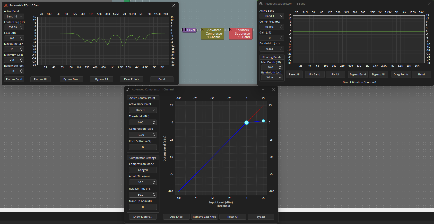
- Open the Ring Out Uber filter - This block contains a starting point HPF and several PEQs that will be used to notch the offending "ring" frequencies.


- Excite the Room - Have a person stand in the presentation area and speak loudly or introduce an impulse.
- Using an FFT tool, identify the first frequency to ring as the PPL Master Gain is increased.
- Apply notch filter - Set the PEQ at the identified frequency with gain of -6 and bandwidth of 0.15.
- Repeat the process until the top 4-7 ring frequencies have been identified and notched. These frequencies will commonly present in the 200 - 1200 Hz range, but are unique to each room and system.
- Once the notch filters have been identified and applied, run the PPL Master Gain up to the edge of feedback again, then engage the Frequency Shift block. Activating this block should provide additional stability.
- Compare this level to the level documented in the Preliminary Test.
If an FFT tool is not available, a Feedback Suppressor block may be a good tool for finding ring frequencies. Be sure to match the filter count to that of the PEQ blocks in the file as this will allow copying DSP data from the locked Feedback Suppressor block to the microphone specific PEQ block.
- This video is a good reference regarding room amplitude response.
Section 4: Final Optimization and Verification
- Verify Gain Shading - While a person is speaking on stage, walk the audience area from front to back. The perceived reinforcement should be smooth, consistent, and natural-sounding.
- Test System Performance - Have the presenter walk throughout the entire designated presentation area. The audio level in the audience should remain consistent.
- Establish Nominal - With the presenter talking with a presenter-level voice, adjust the PPL Master Gain level. The goal is to determine a Nominal level for the system performance as well as an upper and lower usable limit. We expect this range to look something like this:

Max = Nominal +3
Nominal = Nominal
Min = Nominal -3
- Set Limits - Once the usable range limits have been determined, set them in the PPL Master Gain block and save presets as needed. Users of the PPL system will likely benefit from a user-facing control such as TEC-X 1000. This user-facing control should control the PPL Master Gain level and adhere to the defined limits. Keep in mind, each system will have different use cases. Offering this control range allows the user to adjust system performance to meet the changing needs. As the AV Systems Integrator, you know the needs of the user and the system best; please accommodate accordingly.
Section 5: Advanced Tuning Techniques (Optional)
For particularly challenging acoustic environments, the following techniques can provide an additional degree of stability and control.
- Implement a Soft Noise Gate - The available base PPL file includes an advanced compressor configured as a soft noise gate. There are times when enabling this block will be helpful. The following shows the curve in use when enabled, open the meters, and adjust according to system-specific needs:
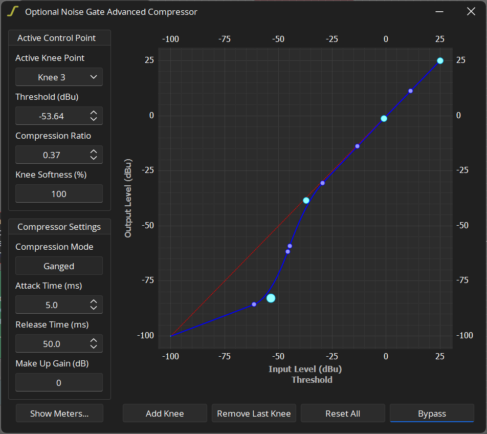
- This can help prevent low-level audience noise or rustling sounds on stage from opening the PPL automixer gate, without being as abrupt as a hard gate.
- Apply a Slow pull-down AGC - The base PPL file also includes an optional AGC block that has been bypassed. If engaged, this block will take a slow 2s average of the PPL microphone signals and apply slight attenuation over time. This dynamic may help smooth the listener experience of different presenters of different loudness and energy levels.

(Optional) Implement Time Delay - For very long rooms and discerning listeners, you may choose to add delay to the loudspeaker zones to improve localization (the perception that the sound is coming from the presenter, not the ceiling). This is an advanced technique and should be implemented with care to avoid introducing audible artifacts.
Section 6: End-User Demonstration
- Establish a Baseline - To showcase the system's effectiveness, have the client listen from the back of the room. Start with the system muted and speak from the stage.
- Demonstrate System Performance - Unmute the system and continue speaking. The lift in intelligibility should be clear but not distracting or sound like a PA system.
- Provide End-User Guidance - Instruct the end-users to stay within the designated presentation area (where the microphone beams are locked) for the best performance. Explain that the system is designed to be automatic and transparent.