CI-1 wiring guide
The CI-1 Control Interface is a companion product to the Vocia® LSI-16 Life Safety Interface. It facilitates the necessary connections to the LSI-16 for standards compliance.
The CI-1 requires 2 x 24VDC 15W power connections. Biamp offers an optional 24VDC 30W inline power supply which is appropriate for use with the CI-1. The power supply supports 100-240VAC to 24VDC and has a 4-pin Phoenix style connector included. The power supply part number is 283.0119.90A. An IEC plug to local wall power cable is also needed for the power supply - in North America the part number is 330.0002.900 (this cable part number will differ for other countries).
All logic input and output connections of the LSI-16 are permanently monitored for open or short circuit. The CI-1 carries most of the necessary terminating resistors to ensure normal operation of the LSI-16, without the need of external cabling. However, some logic connectors are not terminated internally, in order to provide monitored connectivity between the CI-1 and the fire panel or building management system.
This article explains how to terminate the remaining monitored connectors of the CI-1 to get a Vocia system into final operational state.
I/O Connections to be terminated
If there are any monitored logic input or output connections on the CI-1 that are not used, a termination resistor must be installed on them to prevent the Vocia system from indicating a fault. Termination of any input or output is only necessary if they remain unused and won't be connected to any third-party equipment:
- Any output connected to a relay doesn't require terminating resistors.
- Any input connected to a digital or open collector output, doesn't require terminating resistors.
- Any input connected to a voltage-free contact will require a terminating resistor, placed nearby the actual contact.
The following logic outputs require an external resistor (22 kOhm) connected to 24V reference voltage:
- VA = Voice Alarm Active Output
- GF = General Fault Output
The following logic inputs require an external resistor (2.2 kOhm) connected to 24V reference voltage:
- U = UPS Fault Input
- P = PSU Fault Input
- W = EWS PSU Fault Input
CI-1 without termination
By default, the CI-1 comes with all necessary cabling for interconnecting the LSI-16. This is a rear view on an LSI-16 and a CI-1 connected with the supplied interconnection kit:
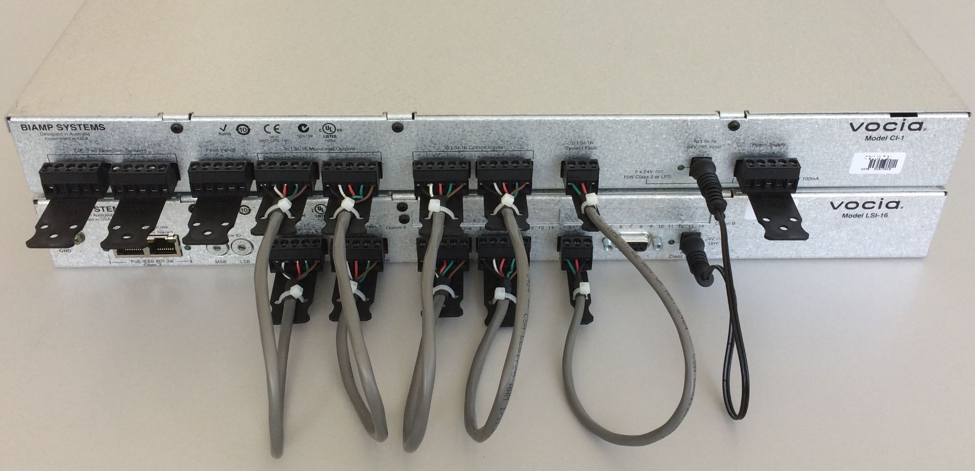
LSI-16 and CI-1 interconnected with supplied accessories
Left in an "out of the box" state, when no additional termination to the CI-1 has been applied, the LSI-16 will report multiple faults in Vocia Software, as seen under LSI-16 > Configuration > Alarms & Logs:
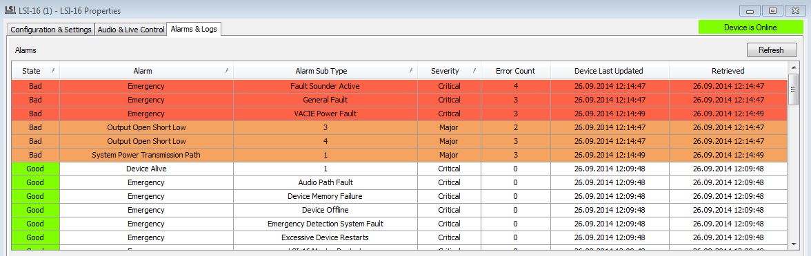
LSI-16 Alarms & Logs without terminating resistors
CI-1 with termination resistors
As mentioned above, there are five I/O pins at the CI-1 that require for external terminating resistors if those pins are not wired to an external device. All of these resistors can be connected to the +24V reference voltage, provided by the CI-1 itself:
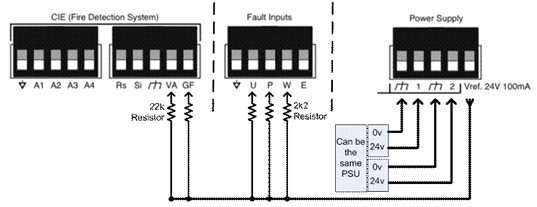
Connecting scheme for required resistors, assuming all five ports are unused
Applied to the actual CI-1 hardware, the finished wiring of the circuit would look similar to the following example:
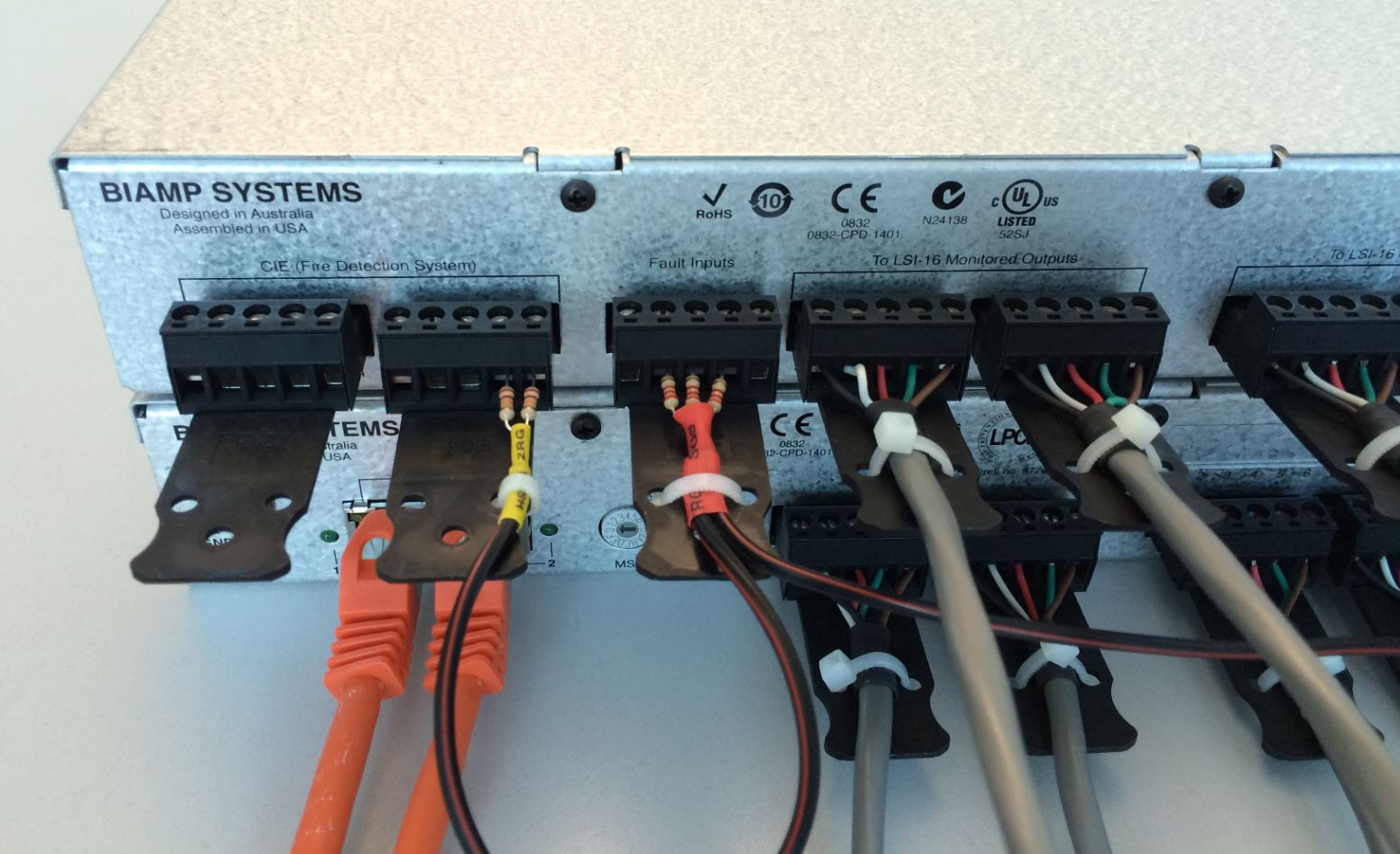
Termination resistors installed on a CI-1
Note the use of (2) 22k resistors on VA and GF and (3) 2k2 resistors on U, P, and W. The five resistors are not all the same value!
With all resistors in place and a 24V backup power source being connected to the CI-1, the software will now clear all faults at the LSI-16 Alarms & Logs section, as long as no other emergency device within the same World is in a fault state.
Further reading
More information on interfacing logic inputs and outputs with third-party emergency equipment can be found here: