LSI-16 setup and wiring guide
This wiring guide explains the instances in which the Vocia Life Safety Interface (LSI-16), the enhanced Life Safety Interface (LSI-16e) and the Control Interface (CI- 1) should be used, and describes the connections that are required for correct operation.
The functionality of the LSI-16/LSI-16e has been tailored to the specific requirements in the EN 54-16 European life safety standard. However, the LSI-16, LSI-16e and CI-1 are still applicable in installations that require highly reliable and fault-tolerant systems with voice evacuation functionality, even if there is no need to meet EN 54-16 standards. Some terms are specific to EN 54-16, for example, General Fault, General Alarm, Protection Fault etc and may not be applicable for your jurisdiction. This document attempts to explain the operation of the Vocia emergency system so it can be used for life safety purposes in other jurisdictions.
Alarm inputs and faults
A “fault” is a problem that may impede the Vocia system from performing its role as a Voice Alarm Control and Indicating Equipment (VACIE), and an “alarm” is a condition that has been triggered via an external stimulus, generally from the fire detection system or Control and Indicating Equipment (CIE).
Alarm Inputs
A Vocia alarm is any input from the fire panel to the four emergency inputs on the LSI-16/LSI-16e (control input pins 5 - 8). The Vocia Alarm state is triggered by a low to high transition on the emergency inputs, with the high state between 14V and 24V. These four inputs are used to connect to the fire alarm control and indicating equipment (CIE) to notify the LSI-16 that an alarm has occurred in a particular zone. When an alarm is detected, the Vocia system will cease normal operation and will enter Emergency Mode. An emergency input on the four control inputs can be configured to mute the zone or play one emergency message (see figure below). Any unused emergency inputs must be terminated, disabled in software or attached to a CI-1.

Additional general purpose inputs for use as alarm inputs are available on the LSI-16e or by adding the IM-16 to the LSI-16. These sixteen general purpose inputs can be programmed to play an emergency message, mute or reset an emergency zone. You can have up to 10 inputs into a single emergency zone (see figure below). The general purpose inputs can be programmed as TTL, high range or monitored high range. Monitoring is available for short to ground and open circuit.
Logic Level Contact closure Active State Low will be used for a Normally Open circuit, Logic Level Contact closure Active State High should be used for a Normally Closed circuit. Input and output states can be monitored in real time on the Audio & Live Control tab for LSI-16 and IM-16.

Faults
Faults indicate a problem in the Vocia system. Depending on the severity of the fault parts of the Vocia system may still be operational. There are three types of faults reported by the LSI-16:
- General Fault: This does not indicate a fault with just any device, it must be a device that is configured and considered part of the emergency system (VA-8600c, EWS-4/10, LSI-16, LS I-16e, and ELD-1). A General Fault indication is generally accompanied by a Path, Protection or Network fault, but not always.
- The LSI-16 will show a General fault if only one CobraNet network connection is present, both must be active.
- Path, Protection and Power Supply Fault: These three faults are grouped together and will initiate a General Fault condition whenever triggered; in some conditions they will trigger a system fault. A General Fault condition will self-clear once the problem has been resolved.
- Path: The path integrity is tested from microphone capsule to the end of the loudspeaker lines (provided an ELD-1 is fitted to the end of the loudspeaker lines). A Path fault will be triggered if a fault in the transmission path is detected.
- Protection: A protection fault is activated if a system amplifier channel fails however this failure will not prevent an emergency announcement being made on other available channels.
- Power Supply: A Power Supply fault will be triggered if the LSI-16 is operating on a PoE supply but the main 24V supply fails or an external power supply fault is signaled to the LSI-16.
- System Fault: This is the most serious condition in a Vocia system and should be acted upon immediately.
Again, this only applies to emergency devices that have been configured in the World that the LSI-16/LSI-16e resides in. In this state the System Fault LED and the General Fault LED will be illuminated to draw attention to the compromised status of the system. All other LEDs on the front of the device will remain off. When a System Fault occurs it will always trigger a General Fault as well. A System Fault will not self clear once the problem is resolved and requires a manual reset from the CI-1 or via a switch which has been connected to the Voice Alarm Reset (pin 4). A System Fault condition is reported when the state of an emergency device cannot be reported to the LSI-16. This has been implemented to maintain system integrity through all Emergency devices.
The following states will trigger a System Fault:
- Any emergency device dropping offline.
- The LSI will not configure.
- The LSI restarts unexpectedly.
- Software fault detected in an emergency device.
- Memory fault in an emergency device.
- Complete or critical LSI failure.
- Immediately after a configuration is sent*
* Upon applying power or immediately after a configuration is sent, the LSI-16 will always power up in the System Fault condition state. Manual intervention is required to take the LSI-16 out of this condition which can be done via a CI-1 or via a custom circuit below (see following section on wiring an LSI-16 to external switches). This power up condition does not prevent emergency zone voice announcements.
Additional fault inputs can be connected using the LSI-16e general purpose in puts (see figure below).

Wiring
LSI-16 with a CI-1
With the introduction of the CI-1 the wiring of an LSI-16 can be done directly from the CI-1. This means that any connections made from the fire detection system or mimic panel are made to the CI-1. Connections are then made from the CI-1 to the LSI-16. In an EN 54-16 installation it is mandatory to have a CI-1. However, in other jurisdictions a CI-1 may not be required, but is always highly recommended as it greatly simplifies wiring.
Biamp offers a 24VDC 30W inline power supply which is appropriate for use with the CI-1. The power supply supports 100-240VAC to 24VDC and has a 5-pin Phoenix style connector included. The power supply part number is 283.0119.90A. An IEC plug to local wall power cable is also needed for the power supply - in North America the part number is 330.0002.900 (this cable part number will differ for other countries).
The CI-1 also negates the need to wire switches to control some important functions, namely the Local Sounder Silence, System Test and System Fault Reset. In addition it provides a Sounder, which is particularly useful in alerting staff to a fault in the Vocia system or when an Alarm was triggered from the fire detection system.
The wiring of the CI-1 is very similar to the LSI-16, except in a few minor ways. To begin with, all of the connections that are found on the LSI-16 (apart from the option module slots) are also found on the CI-1. When interfacing to a fire detection system you still need to wire all of the connections to the CI-1 however for any unused inputs and outputs the CI -1 will provide all of the proper terminations as well. If a Monitored Output is used the installer must disconnect the relevant output from the CI-1 and provide their own 22kΩ resistor at the far end of the line being monitored. See the below figure for LSI-16 and CI-1 interconnects.
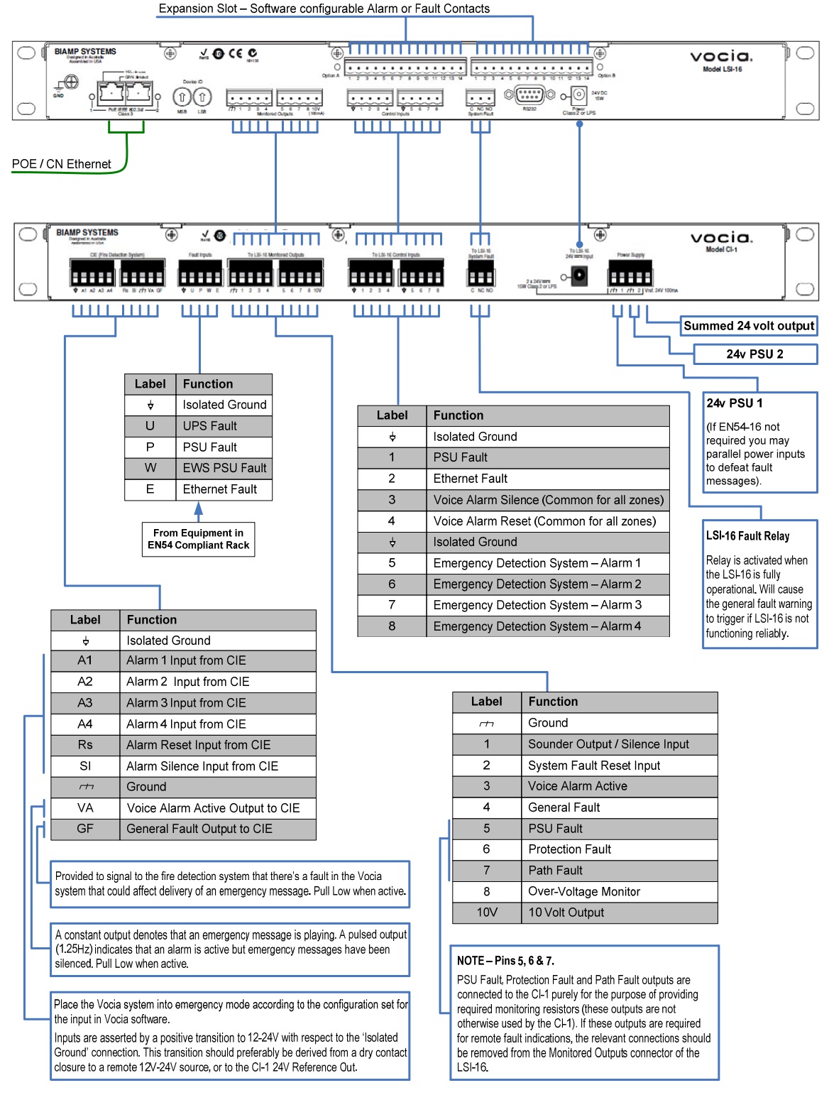
System Fault Relay Connection
The System Fault Relay is used for informing external devices or sounding an alarm that indicates a System Fault has been triggered. The system fault relay connection has both a ‘normally open’ and ‘normally closed’ setting and both may be used at the same time.
LSI-16 without a CI-1
Control Inputs
The figure below shows the recommended wiring when connecting LSI-16 control inputs to an external voltage source, when a CI-1 is not present in the system.

The table below details each control input on the LSI-16/LSI-16e for external connections, when a CI-1 is not present in the system.

Pins 1 & 2: For fault inputs a resistor is not required. These inputs are activated on a high to low transition and by default are in a high state. A fault will be reported once a high to low transition is detected.
Pins 3 & 4: It is necessary to connect the Alarm Silence and Alarm Reset to either the CIE or to a ‘normally open’ switch. There is no alternate method for resetting, or silencing any active Alarms other than this. These operate on a low to high transition and need to be wired to ground through a 3.9k Ω resistor (to pull these inputs into a low state) first.
Pins 5 to 8 : If any of the four Emergency (Alarm) Inputs are not used they must be disabled in the software or an Alarm will be reported. When used they should be wired through a 3.9kΩ resistor to ground. If a normally closed switch is used, the resistor is still recommended to avoid false alarms. If a resistor is used, this alarm condition will be suppressed without actually affecting an alarm condition generated from the CIE. Monitoring of the connection should be handled by the CIE to ensure a valid alarm is reported in an emergency situation. The figure below shows valid ways of connecting circuits to assert the Alarm Inputs.

As Alarm inputs are activated on a low to high transition, a resistor should be used to pull these inputs down first (to a low state) then they become asserted once a low to high transition is detected. If the input is not disabled in the software, a 3.9kΩ resistor wired to ground should be used to suppress alarms.
In its default state the LSI-16 Alarm Input always provides a 3mA current source (high state). This current source is overcome by using the resistor which pulls the current source to ground (low state). Then the 24V is required to overcome this current being pulled to ground and produces the necessary low to high transition. If no resistor is used (in conjunction with a NC switch) the output will be in a low state already. Once the switch goes open circuit, the low to high transition will trigger the Alarm. Be aware that an open circuit or short in the line will also assert this alarm.
For dry contact relays and switches, either provided by the CIE or by the user, we recommend using the 24V supplied circuit shown in the figure below. Battery backing for the LSI-16 is in most cases highly recommended and has been catered for. This 24V supply can also be used to feed a power source to the Alarm Inputs. It is not uncommon for the CIE to also provide a 24V output which can be used as well.

Monitored Inputs/Outputs (I/O)
Monitored Inputs/Outputs achieve their monitoring characteristic by becoming a part of a circuit. This circuit needs to contain a load (LED, Lamp, Sounder etc) and a connection to a power source. If any of the inputs/outputs on terminals 1 through 8 are unused, the input/output must be connected to an external 2.2kΩ resistor and the 10V pin or user supplied power source (to present a pseudo load to the output terminal). If not using a resistor to terminate the connection the maximum resistance of the circuit should be no greater than 22kΩ .
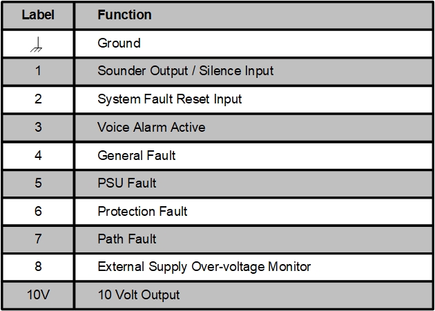
The General Fault, PSU Fault, Protection Fault, Path Fault and External Supply Over-voltage Monitor outputs (Pins 4 to 8) are continuously monitored for:
- Open-Circuit
- Short-Circuit to ground
- Over-Voltage
In addition to the fault monitoring detection circuitry, output pins 3 - 8 are designed to produce output contact closures.
Monitored Inputs/Outputs ‘Sounder Output/Silence Input’ and System Fault Reset Input (Pins 1 & 2) are configured additionally as Inputs. This was done as a specific response to EN 54-16 requirements and so requires the circuit shown below for correct operation.
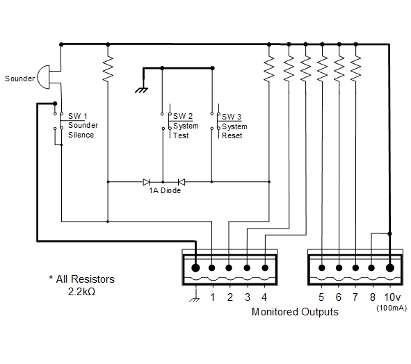
If a visual indication for the state of the output is required the figure below shows various circuits of how this can be achieved.

Internally the fault pin senses the small amount of current supplied from the 10V pin or external power supply. The small amount of current flow through the resistor is enough to keep the fault pin from generating an Alarm. Using the ‘Monitored LED circuit’ as an example, the LED indication will be ‘on’ but the current source will be so low that light will not be visible. Once the LSI-16 output gets asserted, an internal connection to ground is established (shown in below) thus providing a path for the current flow to illuminate the LED.

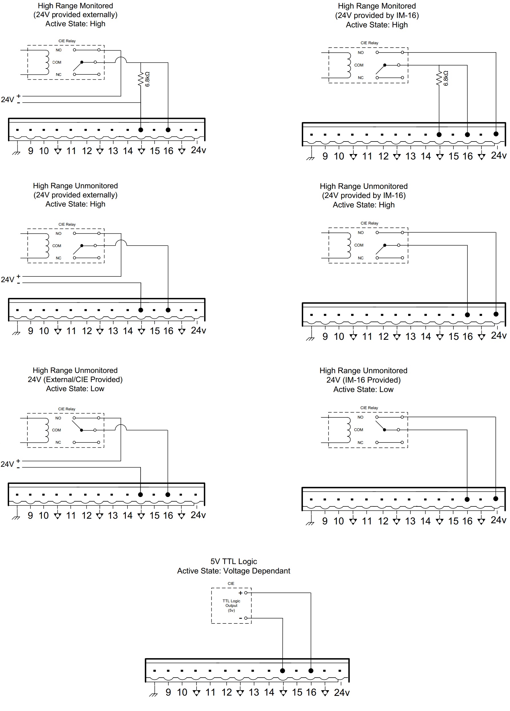
LSI-16e General Purpose Inputs (IM-16)
The IM-16 is designed to supplement the LSI-16. The same option I/O can also be found on the LSI-16e. The connections on the IM -16 (or general purpose inputs on the LSI-16e) can be configured in software as alarm, fault or reset inputs. The user can also use software to configure the connections as TTL, high range or high range monitored. The active state used to assert these inputs can be configured as high or low range, except for the high range monitored instance which is only able to be configured in a high active state.

Suggested Alarm and Fault Input Connection Diagrams
Vocia Software Fault Monitoring
In addition to the front panel LEDs, the Vocia software is continuously updating the current operational state of the emergency equipment (viewable in the Alarms & Log tab of the LSI-16 device dialog window). The following fields are monitored for all Emergency devices in the World in which the LSI-16 resides:
| Fault Name | Fault Description |
| Audio Input Path | Reported by all devices that pass audio, this alarm indicates that the device is not receiving audio correctly, will also set off emergency alarms in any device that is part of an emergency system. |
| Audio Output Path | Reported by all devices that pass audio, this alarm indicates that the device is not transmitting audio correctly. This alarm will also set off emergency alarms in any device that is part of an emergency system. |
| Available | This alarm indicates that the emergency controller for the World is non-functional. Check the LSI-16 for faults. |
| Configuration | Reported by all devices, this alarm indicates that the configuration that is currently stored on the device is incomplete or has errors. Create a valid project file and execute a Send Configuration to resolve this alarm. |
| Device Alive | This alarm is triggered if the device is not fully operational (i.e., if it is not configured, time synchronized, or online). |
| Device Offline | The device is offline. |
| Device Restart | Device restart count. Does not provide indication for possible causes. |
| Device Unknown | Device unknown. |
| Emergency | This alarm is triggered if any of the emergency alarms have been triggered. |
| Emergency Master Restart |
Unexpected restart or power loss of LSI-16 |
| Emergency Memory | This alarm indicates that one of the memory devices essential to correct operation has failed. |
| Emergency State | This alarm is triggered if the system enters emergency mode. The system can only enter emergency mode through external stimulus of an LSI-16, such as a trigger from a fire alarm system. |
| Emergency System Fault | This alarm indicates a system fault in the emergency system. This is a critical error, and the system will be non-operational under this alarm condition. |
| Flash | Reported by all devices, this alarm means that an error has been reported in the flash memory and may be corrupted. |
| General Fault | This alarm indicates a general fault in the emergency system. Check the device's 'Alarms & Logs' tab for active faults. |
| Heap | Internal memory corruption of an emergency device. |
| LSI-16 System Fault | A system fault condition has occurred (refer to Faults above for detailed fault conditions). |
| Network |
This alarm indicates that the device has experienced network communication errors or dropouts. The LSI-16 always needs both network ports to be connected to the CobraNet network to ensure redundant paths are present. They can be connected to the same switch, but best practice in life safety systems is to provide a redundant CobraNet network path. |
| Output Communications | This alarm is triggered if the LSI-16 is unable to communicate with the control output driver. |
| Output Open Short Low | This alarm is triggered if one of the LSI-16 control outputs is shorted to ground. |
| Output Short High | This alarm indicates that one of the LSI-16 control outputs is shorted to a power supply rail. |
| Output Temperature | This alarm indicates that the control output driver has a thermal fault. |
| PoE |
Reported by all devices that rely on PoE (VA-8600 and MS-1 do not require PoE), this alarm indicates The LSI-16 allows suppression of PoE faults on one or both of the network ports if PoE is not expected to be present. |
| Power | This alarm is triggered by a fault with a configured UPS that is connected to the LSI-16 for the applicable World. |
| Protection | VA-8600 AM-600 audio output card failure. |
| Remote Configuration | This alarm is triggered if one of the remote devices in the emergency system is not configured. |
| Remote General | Fault occurred on an emergency device other than the LSI-16. |
| Remote Memory | This alarm indicates a memory fault in one of the remote devices (EWS-4, EWS-10, VA-8600, VO-4e, ...). |
| Stack | The stack alarm indicates a corruption of the internal memory used in the device. |
| System Power | This alarm indicates a fault with the primary DC power supply to the LSI-16. |
| System Power Transmission Path |
This alarm is triggered if the LSI-16 power supply transmission path has been interrupted. |
| Transmission Path | This alarm indicates a fault with the emergency transmission path, which can be either an Ethernet control data connection or an audio path. |
Further reading
This document is designed to be a guide to the way the LSI-16, LSI-16e and CI-1 interface to a fire detection system. Biamp has also published a VACIE (Voice Alarm Control and Indicating Equipment) manual as required for EN 54-16 certification in addition to the product manuals for the LSI-16, LSI-16e and CI-1. Please refer to this guide for more in depth information on installing EN 54-16 systems and the interconnects of these devices.
The documents can be found at https://www.biamp.com/products/vocia