Connecting to a Vocia system without an MS-1
The process of connecting to a Vocia system is different depending on whether or not a Vocia MS-1 message server is present in the system. This article explains how to Connect to a Vocia paging system that does not include an MS-1 message server. There is also a video at the bottom of this article that demonstrates the process.
Prerequisites
Hardware required will be:
- Biamp Vocia devices, including at least one input device (PS-xx, DS-xx or VI-xx) and one output device (VO-x or VA-xxxx).
- One computer configured with windows 7 or later and configured with Vocia software.
- An unmanaged 802.11af POE Ethernet switch.
- Cat 5e/6 patch cables
Configure Hardware
- Set all device ID’s of the same device type to unique ID numbers. Device ID switches should be set using a 2.5mm (0.1”) to 3.0mm (0.12”) flat blade screwdriver. By default each device will ship with an ID of ‘01’ so you will only need to adjust devices that appear more than once on the network.
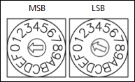
Please note that an ID setting of ‘00’ is invalid.
- Plug all Vocia network devices into the Ethernet switch. Plug the computer into the same switch.
- Power up all the devices including the computer.
Configure Software
Send a New Project File
- Open the software and create a new project or open an existing project. When creating a new project select the correct network adapter that is connected to the Vocia devices.
- In an existing project these settings can be adjusted in Tools > Options > Environment > Default Network Card or Tools > Options > Project >Network Card
- Select ‘Online’ or press ‘F10’ - the Vocia software will communicate via the GUI to any Vocia devices on the network. Any devices not in the layout will be discovered.
- When there is no MS-1 in the system, communication between the GUI and Vocia devices is done via CobraNet. As this is a layer 2 protocol, the IP address of the PC is not relevant. If the GUI does not see any network devices, check any connections.
- Add the network devices in the relevant areas of the design tree or open the discovered devices viewer and add all devices.
- Configure all devices as required.
- Send configuration.
Extract an Existing Project File
- Open the software and create a new project or open an existing project. When creating a new project select the correct network adapter that is connected to the Vocia devices.
- In an existing project these settings can be adjusted in Tools > Options > Environment > Default Network Card or Tools > Options > Project >Network Card
- Select ‘Online’ or press ‘F10’ - the Vocia software will communicate via the GUI to any Vocia devices on the network. Any devices not in the layout will be discovered.
- When there is no MS-1 in the system communication between the GUI and Vocia devices is done via CobraNet. As this is a layer 2 protocol the IP address of the PC is not relevant. If the GUI does not see any network devices, check any connections.
- Open the discovered devices dialog and select all devices. Add them to the project.
- The devices will be shown in the main layout. The Configuration Status will be shown in Yellow which indicates the software and Hardware are not in sync.
- Go to Network > Extract Configuration and the network configuration will be updated to the software.
- All device Configuration status should be green.