Vocia speaker line monitoring
Vocia offers several different ways to monitor the integrity of speaker circuits and report when there is a problem that might prevent a page from being heard. This article describes features and applications of the ELD-1 versus the PLD (PLD-1 and PLD-2) for the Vocia system.
ELD-1
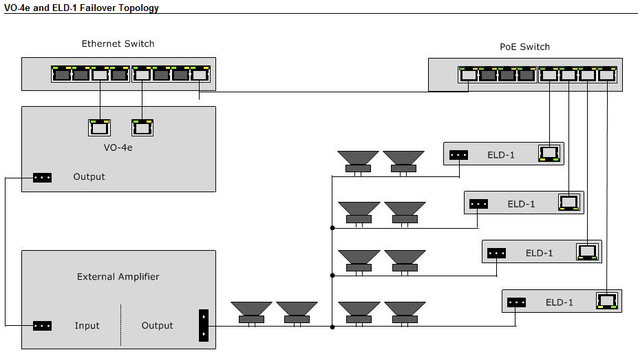
 Vocia End of Line Devices (ELD-1) are designed to be used in conjunction with Vocia amplifiers and output devices (VO-4e) to confirm the integrity of a speaker line. The ELD-1 monitors out-of-band high frequency tones (21kHz - 23kHz) to detect speaker line integrity. The ELD-1 is limited to speaker cable runs of 500 feet or less, greater lengths may prevent correct operation of the ELD-1 and Ground Fault monitoring capabilities.
In contrast to most other devices in the Vocia product range, the ELD-1 does not require setting a Device ID. ELD-1 devices are associated to their host output device and channel in the software while online with the system. It is important to make note of MAC addresses of ELD-1 devices on each speaker line during installation for later reference as identification and association in software is made by MAC address.
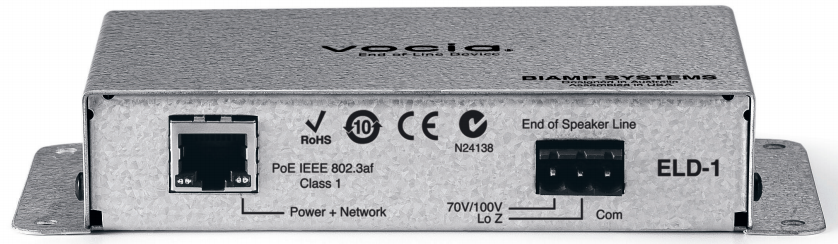
The device has 2 required connections: one is RJ-45 to the Vocia CobraNet network with PoE power and the other is a 3-pin Phoenix connector which must be tied into the end of the speaker line.
Network connection
The Ethernet connection carries control data as well as Power over Ethernet (PoE). PoE-enabled network switches or PoE midspan adapters must be used to power the ELD-1. These must be 802.3af compliant.
The maximum distance between any ELD-1 unit and an Ethernet switch is 328 feet (100 meters) when using copper cabling. Additional Ethernet switches and/or fiber-optic cable can be used to further extend distances between units on a network.
CobraNet allows a maximum of 7 hops between devices. If other network traffic shares an Ethernet switch with the Vocia network, a managed switch should be used with separate VLANs.
Speaker line connector
A plug-in barrier-strip connector on the ELD-1 connects the device to the end of the speaker line. The ELD-1 is limited to speaker cable runs of 500 feet or less as greater lengths may prevent correct operation of the ELD-1 and Ground Fault monitoring capabilities.
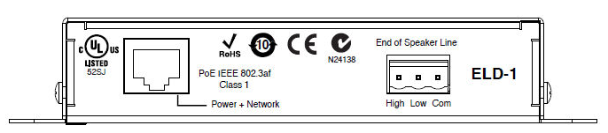
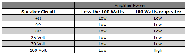
The device needs to be connected to an appropriate monitoring point on the speaker cable. Typically this is after the last speaker on the line. The speaker line should be physically connected between the Com pin and the appropriate Low or High pin as defined in the table below.
The Hi terminal is designed for 100V/70V speaker lines and has a pad to attenuate the audio signal. The Low is for 4 and 8Ω speaker lines and therefore has a smaller pad.
For circuits connected to the Low terminal, the ELD-1 presents:
- 0.5 Watt loading to a 70V circuit
- 1 Watt loading to a 100V circuit.
If the ELD-1 shows failures when connected using the High terminal but works on the Low terminal it suggests that the high frequency content is attenuated beyond the ELD-1’s operating limits or there is a marginal signal present.
Wiring
Vocia ELD-1 devices monitor out-of-band high frequency tones (21kHz - 23kHz) to detect speaker line integrity.
Speaker cables contribute to load impedance; you must be sure to choose cables whose resistance is appropriate for the load and cable length. If using these devices with long speaker cables, choose low capacitance cables so that ELD-1 tones are not excessively attenuated.
The ELD-1 may not function properly if the test tones are attenuated to the point that they are interpreted as being faulty. Possible causes of incorrect faults being reported may include:
- Cable runs in excess of 500 feet.
- Cable gauge is too small for the distance.
- More than XX speakers in the series. XX is a value which is a variable depending on the length of the run, draw of the speakers, and headroom in the system.
Output fault detection
The amplifier monitors faults on speaker connections using a combination of multiple out-of-band (inaudible) high frequency tones for end-of-line detection.
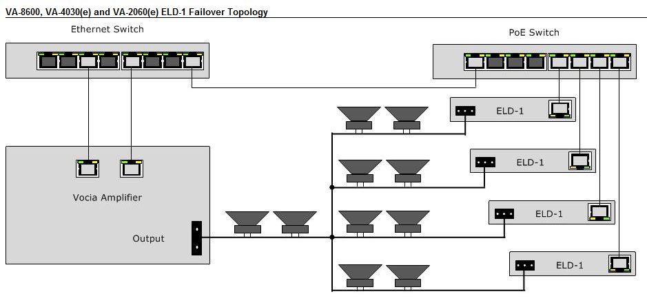
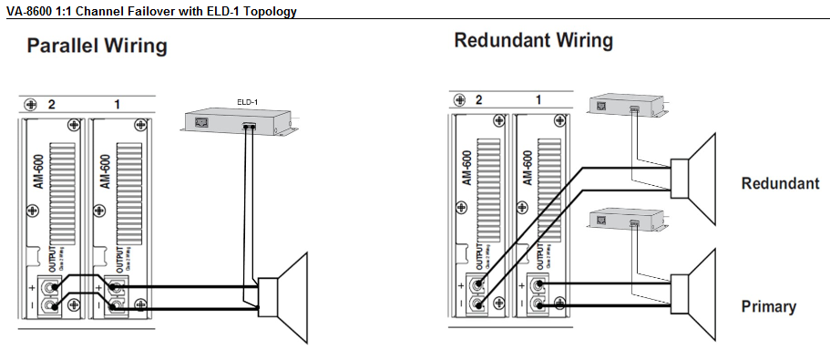
For end-of-line detection, one or more (up to 15 maximum) ELD-1 units must be connected to the end/s of the speaker line. End-of-line and ground fault detection may be individually enabled/disabled in the Vocia software.
To prevent the possibility of interference with these monitored tones:
- Recorded audio messages or audio content with continuous or swept tonal components (e.g. alert tones) should be band limited at 15 kHz during recording
- Program signal level should be adjusted to minimize clipping as severely clipped signals may also affect the out-of-band fault detection tones.
- The use of shielded speaker cable is not supported. Over longer cable runs, shielding can cause a significant increase in the capacitance of the cable, which can lead to the loss of high frequency signals.
- Highly capacitive speaker lines or loads may prevent correct operation of the ELD detection system
- Legacy monitored speaker circuits that use capacitors and resistors or similar methods must have all legacy monitoring circuitry removed for correct operation of the ELD detection system
- If legacy speaker systems and speaker wiring are to be re-used, these must conform to the requirements herein;
- Any external amplifier equipment must be capable of relaying the out-of-band fault detection tones to the ELD-1. For reliable performance a frequency response of better than -3dB at 24kHz must be supported through the amplifier and all speaker wiring up to the End of Speaker Line connections on the ELD-1s
- The amplifier gain or level control must be set so that the nominal output level from the VO-4e (-10dBu, 0dBu or +4dBu; as set in Vocia software) delivers an output level from the amplifier 6dB below the amplifier maximum output level (clip level). This setting must be accurate and must remain constant for predictable operation of ELD-1 units
- For EN54-16 compliance, one or more ELD units must be fitted. End of Line detection must be enabled in the Vocia software.
Fault indication and unit identification
If there is a fault with an ELD-1, the ELD-1 Assignment tab in the Amplifiers properties can be used to identify which ELD-1 is reporting the fault condition.
When a fault is detected on the speaker line or amplifier channel, the lower left LED on the RJ-45 socket will illuminate Amber and remain on until the fault is resolved. Provided a valid PoE power source and Ethernet connectivity are available to the ELD-1 the solid amber indicator can be used to physically identify the ELD-1 that is reporting an issue.
Always make sure that the Vocia system is running the latest software and firmware updates.
PLD
 The PLD (Passive Line Device) comes in two models, the PLD-1 and the PLD-2.
The PLD does not have a network connection.
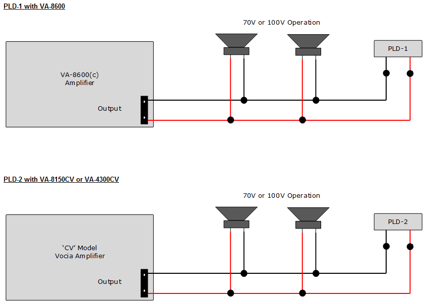
The PLD is designed to be connected directly to the speaker terminals at the end of the speaker line. It is restricted to 70V and 100V constant voltage configurations and up to 300 Watts (100V) and 150W (70V) output power.
Identification
The device is fitted with two 18AWG insulated conductors, 250 mm long. To identify the different models a color scheme has been implemented on the leads. The PLD is presented in two variants to accommodate the different characteristics of the amplifiers.
- The PLD-1 has white wires and is used for constant voltage (CV) applications and monitors up to 3 impedance bands. It is used with the VA-8600 and VA8600(c).
- The PLD-2 has yellow wires and is used for constant voltage (CV) applications and monitors up to 4 impedance bands. It is used with the VA-4300CV and VA-8150CV.
Wiring
PLD's can support loudspeaker cable lengths of up to 4265 feet (1300 meters or 1.3km). Use of the PLD on speaker lines over this distance is not supported due to the large amount of variables involved, including speaker type, speaker placement, cable type, cable gauge and the installation environment. Appropriate gauge and reference ceiling speakers loading must also be used for this limit to be achieved.
Note the PLD cannot be used with multiple branch speaker lines or with Low-Z output amplifiers.
PLD devices are not supported on speaker lines configured over a maximum wattage. For 100V lines over 300W or 70V lines over 150W, an ELD-1 is required. If a PLD is used on a speaker line that has been configured over over the maximum power ratings, the accuracy and reliability of the PLD cannot be guaranteed.
Configuration
The setup and calibration of the PLD is done via the ELD Assignment tab of the amplifier. The configuration for the PLD triggering failover is done via the Options tab > ELD Fault Triggers Failover. In contrast to most other devices in the Vocia product range, PLD's do not require the setting of a Device ID or require a network connection.
Configuration of a PLD device is a two-step process:
First you need to enable a PLD on a channel. PLD’s can be enabled on a per channel basis by the checkbox in the PLD column
Second you need to run the characterization / detection process. The characterization process will allow the amplifier to detect the PLD on the speaker line.
PLD detection is performed by pressing one of the ‘Calibrate’ or ‘Recalibrate All’ buttons. This will trigger all channels with a PLD enabled to perform a characterization / detection cycle with pink noise. After the pink noise, the impedance curve for the appropriate frequency area will be used to determine the centre frequency to be used. Once the centre frequency is found, a Tone Test will be performed to calculate the nominal impedance and bandwidth for the PLD. This information will then be used to configure the Impedance Monitoring Band which is used to detect the PLD. If the PLD cannot be found in the impedance curve then the PLD status will show ‘PLD Detection Failed’. The button ‘Recalibrate All’ will allow calibration on all channels configured to use PLD’s even if they have been calibrated already. The Status column will display the state of the PLD before, during and after the characterization / detection process.
The PLD will support auto-characterization of the speaker line from Vocia software 1.7 forward, however prior to 1.7 any speaker line being used with this device will require manual configuration. Note that prior to Vocia version 1.7 a validation error will not be given and the user will not be prevented from sending the configuration. Please contact Biamp support if needed.
Band limiting
When PLD's are being used, recorded audio messages or audio content with continuous or swept tonal components (e.g. alert tones) should be band limited at 15 kHz during recording. This allows the HF impedance monitoring to function properly.
ELD-1 vs PLD-1
It is permissible to use a combination of PLD and ELD devices within one Vocia system, even on different channels of one amplifier. It is not possible to use both PLD and ELD devices on the same amp channel.
|
ELD-1 |
PLD Impedence Monitoring |
|---|---|
| Uses out-of-band (inaudible) tones to monitor the speaker line |
Uses tone or program material to excite the line (audible and level dependent). The audio must contain frequency components in the configured bands of interest. |
| Reports shorts or opens in the speaker line |
If the impedance falls below or above a threshold then a fault will be reported. If a change in the speaker line impedance is not enough to exceed the threshold an Fault will not be indicated. I.e a speaker failing on a long speaker run may not present enough of a change to be detected. |
|
Software and physical LED Fault indication. |
Software only Fault indication. |
|
‘Branched’ speaker lines are supported. You can have up to 15 ELD’s per amplifier output. |
‘Branched’ speaker lines not supported. You can have only 1 PLD device per amplifier output. |
|
Compatible with both constant voltage and low impedance systems. |
Compatible with 100V constant voltage systems up to 300 watts or 70V constant voltage systems up to 150 watts. |
|
ELD-1's can support speaker runs up to 500 feet (152.4 meters). |
PLD's can support loudspeaker cable lengths of up to 4265 feet (1300 meters or 1.3km). |
Common causes of 70V / 100V amplifier faults
Typically if the amplifier is clipping, distorting, or shows faults indicating a short or "drawing too much power" it indicates the circuit has been overloaded. Often these faults will appear only during a page or while the amp is under load.
Common causes of faults include one or more of the following:
- a high pass filter is not being used, resulting in too much low frequency audio trying to be pushed through the transformer, causing a short or overload. 70V and 100V circuits typically require a high pass filter (HPF) at 75Hz or higher to prevent saturating the transformers.
- system lacks a compressor / limiter, properly configured to prevent overdriving the outputs
- input signal to the amplifier is too high, or the amplifier's input gain is too high, clipping the outputs.
- too many speakers are on the circuit or are tapped so the overall watts required is greater than the amp channel can supply
- one or more speakers is in 8-ohm mode or is accidentally tapped at too high a wattage
- the speaker wire is too thin
- there is a physical short in the line - a nail or screw driven through the wire, a sliced wire caused by rough installation, etc.
- the branch circuits in the speaker line have been connected improperly, resulting in an overloaded circuit
- the amplifier must be designed for 70V / 100V use or have an output transformer attached in line