TesiraXEL Amplifiers - Asymmetrical Power Bank Applications
The TesiraXEL 1200 series amplifier allows users to configure output power on a per-channel basis. This article describes how this functions and offers insight into how to determine what power levels are needed for a particular application.
Asymmetrical Power Banks and definable output type
The TesiraXEL 1200 amplifiers are Class-D amplifiers that support variable, asymmetrical power bank allocation.
The power bank feature allows users to custom-tailor the per-channel output power of the amplifier to the needs of the job. Traditional amplifier topologies were limited to a fixed per-channel power output, which often resulted in having to over-purchase per-channel power to meet the needs of a few high-current channels, leaving other channels over-provisioned.
Biamp's flexible design allows one amplifier to be configured to fill many roles, reducing the number of product SKU's that might need to be specified for a project. A traditional amplifier lineup may have included 5-10 models to fill a variety of niches. The TesiraXEL 1200 family can fulfill these roles with just two models:
- TesiraXEL 1200.1 : 1200W total chassis power, (1) 1200W power bank feeding (4) channels.
- TesiraXEL 1200.2 : 2400W total chassis power, (2) 1200W power banks feeding (2) channels each.
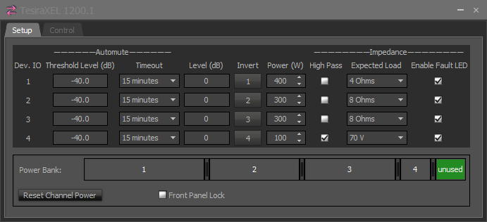
The TesiraXEL 1200 amplifiers default to having all channel outputs symmetrically balanced (300W per channel on the 1200.1; 600W per channel on the 1200.2).
Users can alter the channel power balance as needed, specifying the per channel output in 1W gradations. Using the amplifier's full power bank reserve is not required. The amplifier will not exceed the output settings you apply per channel.
Each output is also individually configured by speaker driver type, with 4-ohm, 8-ohm, 70V, and 100V supported. Output channels cannot be bridged for 2-ohm or other applications.
You may use one or all channels of the amplifier and assign as much or as little power as desired from the power bank resources. Below are just a few examples of how power allocation can be configured on a TesiraXEL 1200.1:
- All 1200W to 1 channel (3 channels at 0W)
- 600W each to 2 channels (2 channels at 0W)
- 600W to 1 channel and 300W each to 2 other channels (1 channel at 0W)
- 575W to 1 channel, 150W to another channel, 375W to the 3rd channel, and 100W to the 4th channel
You may also mix and match speaker driver types between channels. For example, a TesiraXEL 1200.1 could be configured as follows:
- Ch 1: 400W output at 4 ohms
- Ch 2: 300W output at 8 ohms
- Ch 3: 300W output at 8 ohms
- Ch 4: 100W output at 70V
- In this example, channel 4 can be used for a run of up to (18) 70V speakers tapped at 5W (it's generally recommended to leave 10% headroom in 70V systems). There is still unused power available if needed.
Class-D amplifiers are very power-efficient by design. When idle, the TesiraXEL 1200 amplifiers draw just 51 watts at 120V.
How much output power is needed?
To determine your power needs it is generally best to work backward from the listener position to the amplifier. You'll want to know all of the following:
- Average target volume at the listener position (dB-SPL)
- Distance from the listener to the speaker
- Speaker's rated sensitivity (expressed as dB-SPL/1W/1m)
- Expected crest factor of your program material
You can also check your calculations with our Amplifier Power Calculator.
Speaker sensitivity
Speakers are rated by their sensitivity, or how much sound they produce for a given amount of power input. This is shown on their data sheet as dB-SPL/1W/1m, which is read as "the volume (dB-SPL) that will be produced by the speaker when powered with 1W and measured at a distance of 1 meter."
To increase volume by 3dB, the amplifier wattage needs to be doubled, to increase another 3dB the amplifier wattage needs to be doubled again. Buying a speaker with a good sensitivity rating rather than a poor one may be the least expensive way to output additional acoustic power.
- 2x increase in amplifier power yields a 3dB increase in volume.
- 4x increase in amplifier power yields a 6dB increase in volume.
- 16x increase in amplifier power for a 12dB increase in volume.
- 64x increase in amplifier power for an 18dB increase in volume.
- 256x increase in amplifier power for a 24dB increase in volume.
Constant Voltage
In constant voltage distributed systems, step-down transformers or autoformers are attached to traditional 8-ohm or 4-ohm speakers. The step-down transformer or autoformer takes a high-voltage, low-current input and transforms it into a low-voltage, high-current signal for the speaker voice coil. Low-output amplifiers require a step-up transformer to power the line, while other amplifiers (such as the TesiraXEL amplifier) are able to directly drive the line and do not require a separate step-up transformer at the supply side.
Speaker output transformers or autoformers typically have multiple taps. Each tap is connected to a different input winding around the core, resulting is a different load presented to the amp and a different output power at the connected speaker. Taps are labeled by wattage. It is common to see each tap "step" double the wattage, or increase acoustic output by 3dB. This allows speaker volumes to be balanced by changing the tap used.
Calculation of the power required is made through simple addition of all connected taps on the line. It is generally recommended to specify 10-20% of overhead for the amplifier to allow for volume balancing and other variables. For example, if you plan to drive 20 speakers tapped at 5W each for a total of 100W, it is recommended to use a 110W to 120W amplifier.
When planning a constant voltage system, you will also need to know the voltage rating of the transformers (70V or 100V). This refers to the maximum voltage the amplifier will supply: a 70V system will supply a maximum of 70V RMS, while a 100V system will supply a maximum of 100V RMS. During periods of quiet content, only a few volts may be on the line, while at maximum volume the amplifier will supply the maximum voltage. All connected speakers must use transformers with the same voltage rating as the amplifier.
Amplifier output is most accurately defined by its voltage. Knowing this and the attached load allows you to calculate the watts being produced (e.g., 2.83V into an 8-ohm speaker yields 1W).
For a speaker rated at 90dB/1W/1m, the expected output SPL at a given distance can be calculated for a particular tap. If users will sit at 2m, then the distance is doubled from 1m, resulting in a -6dB drop equal to 84dB/1W/2m.
HPF on constant voltage systems
It is generally recommended to apply high pass filters (HPF) to the outputs of a constant voltage speaker system. This is done to protect the transformers from becoming overloaded or "saturated" by low-frequency content. Every transformer has a saturation point, which defines the limit of low-frequency signals it can pass. TesiraXEL amplifiers offer a fixed HPF which is automatically enabled when a 70V or 100V output is selected. It applies a 70Hz 48dB/octave (8th-order) Butterworth HPF. It can be defeated if desired using a checkbox in the Setup dialog window. A 16Hz 48dB/octave Butterworth filter is activated if the 70Hz filter is defeated, to protect against DC conditions.
Higher quality transformers can pass lower frequencies at higher volumes than inexpensive transformers, but all transformers have a low-frequency limit. When low-frequency signal response is required, it is recommended that transformers are not used.
At the saturation point, resistance increases dramatically in the transformer. If enough power is being pushed into it, the transformer will present a short-circuit to the amplifier.
Saturation means that the transformer cannot pass all of the low frequency energy between the windings properly. The excess, undissipated energy results in heat building up in the transformer (and transmission lines). This will result in non-linear acoustic output. It may cause the transformer windings to overheat, potentially to the point of generating a physical short, or it may cause the amplifier to go into protect mode or fail altogether (if it lacks sufficient protection features). Once the problem frequencies are filtered out and power is reduced then the short-circuit should clear (if the transformer has not failed).
If transformers are simply overloaded due to excessive input power, the observed behavior will be similar to-low frequency saturation.
TesiraXEL will detect overloads and will attenuate to protect itself from short circuits, and will report these issues in event logs and via front panel and software indications. The front panel fault LEDs can optionally be suppressed for impedance faults.
Current draw
TesiraXEL 1200.1 is UL rated at 110 - 240 V ~ 50/60 Hz, 5.5 - 2.3A
TesiraXEL 1200.2 is UL rated at 110 - 240 V ~ 50/60 Hz, 10.0 - 4.6A
For specific heat calculations please refer to Biamp's Heat Dissipation Calculator.
Limiters
 Audio signal limiters
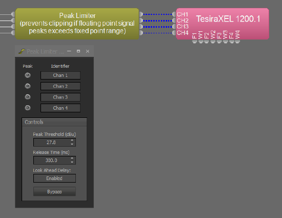
It is highly recommended to place a limiter block as the last step prior to the amplifier.
This is a different application than using a limiter to protect driver components. The intent is to prevent clipped audio signals from being encoded as AVB for passage to the amplifier.
All Tesira DSP uses floating-point processing internally. When audio gets to the output of any DSP device it will be converted to fixed-point notation for the output; this is true for AVB, Dante, CobraNet, VoIP, HDMI, USB, and analog outputs. Floating-point allows for gain above 0dB-FS, while fixed-point hits a hard clipping point at 0dB-FS. Any data above 0dB-FS will be presented as a clipped, truncated, or squared wave to the next device. It is possible to safely exceed 0dB-FS in the Tesira DSP (or any floating-point processor) so long as the signal is brought back below 0dB-FS prior to the output.
The limiter processing object acts as a safety: if a signal is exceeding the limiter threshold, it will compress it (using effectively an infinite:1 ratio) and not allow the clipping waveform to pass.
Enabling Tesira's "look ahead" feature adds 1ms to the latency, but allows the limiter to analyze the signal before it passes. If the signal exceeds its threshold, the limiter will act "instantaneously." Without look ahead, there would always be a slight portion of the clipped signal that passes the limiter before it has time to respond to the unwanted clipping.
Tesira meters refer to level in dBu. Using a peak meter, the clipping level is +28.0dBu. Setting a limiter threshold below that level will prevent sending digitally-clipped signals out of the DSP. Digitally-clipped means that the floating-point notation has forced out-of-range notation to the fixed-scale path. A peak threshold setting about 28dBu is generally safe for full-range content. A release time of 15ms is generally a safe starting point for full range content. If heavy low-frequency content is being used then a longer release time and lower threshold may be desired.
Output processing library file
A Tesira processing library (.tlf file) of speaker output processing components can be downloaded here and imported to your Tesira Processing Library.
Amplifier hardware protection limiters
The final stage of protection is in the amplifier. The purpose of this protection is to prevent the amplifier from being overheated or otherwise damaged by an unexpected current surge or load on the outputs. This is a hardware protection feature to save the amplifier; it is not meant necessarily to protect the connected speakers, which is the responsibility of audio signal limiters.
TesiraXEL 1200 amplifiers employ an average power limiter on the output rails that prevents sustained output power beyond channel limits. The average power limiter measures output power directly, ensuring it works correctly regardless of what load is connected.
For example, a channel configured for 100W into 8 ohms will not drive 400W into 8 ohms, regardless of the nature of the program material, as the average power limiter will constrain it. If a 4-ohm load is accidentally connected the output, levels will be higher than expected, up to the 100W channel maximum set by the user.
Additionally, the amplifier modules themselves have output short-circuit protection.
Maximum rated output
A full-scale peak burst via AVB will result in delivery of the maximum rated output power, as defined by the user for that channel when the correct loudspeaker load type is connected.
There are three important caveats:
- An audio limiter should always be used in the DSP layout to prevent sending a digitally clipped signal to the amplifier.
- Signals in excess of 0dBFS are digitally clipped, but peaks can be easily avoided with a properly configured limiter.
- If the program material is clipped, the output power can temporarily exceed the channel’s power rating. The absolute worst-case scenario of this is a full-scale square wave, in which case the output power will initially be 2x the channel’s rating until the hardware's average power limiter engages.
- If an incorrect, lower-impedance speaker is connected, power output will be higher than expected until the average power limiter engages at the channel's defined maximum output level.