TesiraXEL Amplifiers - Chassis
This page describes various functions of the TesiraXEL 1200 series amplifier hardware. It covers the front and rear panel controls, as well as connections with which the user may need to interact. It also discusses correct wiring of the GPIO connections, with respect to their default sleep and chassis mute behaviors.
Front panel
Front-panel buttons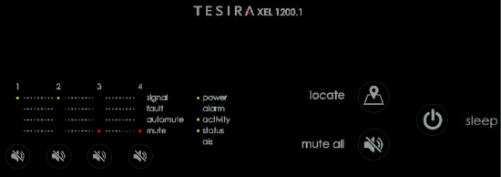

The 1200 series amplifiers feature capacitive touch buttons for front panel functions.
Button Lockout
There are three methods for enabling and disabling chassis front panel button lockout to prevent accidental triggering of mutes, sleep, or Audible Locate functions. Lockout can be enabled and disabled via a simultaneous 2-second press-and-hold of any two front panel channel mute buttons, by using the checkbox in the amplifier's control panel Setup tab within Tesira software, or via TTP command.
Channel Mute
Amplifier channels can be individually muted or unmuted via four dedicated front panel buttons.
The front panel can be locked and unlocked by a 2-second press-and-hold of any two front panel channel mute buttons.
Mute All
All 4 amplifier channels can be muted as a group via the "mute all" button. Channels may be unmuted via the individual channel mute buttons.
- If any channels are currently unmuted, the "unmute all" button will mute them.
- If all channels are currently muted, the "unmute all" button will unmute all of them.
Sleep
The amplifier chassis can be put into a low power (2.5W @ 120V) sleep mode and woken using the dedicated front panel button. A GPIO function can also be used to remotely trigger sleep / wake status via GPIO pin 4.
Locate
To assist in verifying connected cable runs and speakers, the 1200 series amplifiers use Biamp's Audible Locate function.
When activated via the chassis front panel or Tesira software, the Audible Locate feature will play out a spoken-word message on each channel sequentially, identifying the channel by number. The active amplifier channel will indicate signal present via its corresponding "signal" LED on the front panel.
The front panel LED ladder (alarm / activity / status / ais) will also flash for assistance in locating the selected chassis in a rack.
The message can be initiated from the amplifier front panel even when no configuration file is loaded to the system or if the amplifier is disconnected from the Tesira system. This allows cabling to be verified prior to the full system configuration being complete. With no configuration file, the amplifier will utilize a default setting state. In this default state, the amplifier is allocated to 300W @ 8-ohms per channel (1200.1) or 600W @ 8-ohms per channel (1200.2) and the Audible Locate is defaulted to -40dB. This should provide a safe working minimum level to verify the amplifier output without damaging speaker components. It is not expected to properly drive a 70V or 100V speaker line in this default state.
When the amplifier is configured it is possible to vary the level of the message playback from the default of -40dB by clicking on the level in the Locate Devices dialog.
Audible Locate can be deactivated either via the Tesira software or amplifier front panel.
Front-panel LEDs
The TesiraXEL 1200 amplifiers have twenty-one LED status indicators on the front panel. The meaning of each indicator is described below.
Front panel LED activity descriptions for all Tesira devices can also be found in the Tesira Help File.
Device Status
| LED | Off | Green | Yellow | Red |
|---|---|---|---|---|
| Power | Device is not powered | Device is powered | Amplifier is in sleep mode | -- |
| Alarm | No fault is reported in this device (when device is powered) | -- | Minor fault is reported in this device | Major fault is reported in this device |
| Activity | -- | Device is active and properly configured and audio has been started | -- | Audio is stopped on a configured device or the device is unconfigured |
| Status | -- | Device is configured and is part of a system or ready to participate in a system | Device is not configured but is ready to receive a configuration | Device not ready to receive a configuration |
| AIS (Alarm In System)* | No fault is active in any device in the system (when device is powered) | -- | Minor fault is active in a device in the system | Major fault is active in a device in the system |
* The AIS (Alarm In System) indicator will illuminate on all devices in a Tesira system whenever a fault is detected on any device in the system. The AIS (Alarm In System) LED is not included on Tesira expanders.
Channel State
| LED | Off | Green | Yellow | Red |
|---|---|---|---|---|
| Signal | Input signal not present or device is in standby | Input signal present | Input signal present; output attenuating | Input signal present; output clipping detected |
| Fault | No fault is reported in this channel or device is in standby | -- | Minor fault is active in this channel | Major fault is active in this channel |
| Automute | Channel is not in automute | -- | Channel is in automute | -- |
| Mute | Channel is unmuted or device is in standby | -- | -- | Channel mute is active. |
Note: LED notifications of impedance faults can be suppressed via software option on a per channel basis. This affects the Fault, Alarm, and AIS indications.
A list of fault messages can be found in the Tesira Help file under Fault Reporting.
Cooling Fans
Air is ducted from front to rear of the TesiraXEL assisted by 2 variable speed fans. There is no filter. The amplifier is expected to be installed in a clean environment. If construction dust or other airborne contaminants are expected the amplifier should be shut down and protected from debris. Thermal properties can be calculated using the Power Draw and Heat Dissipation calculator.
Rear Panel
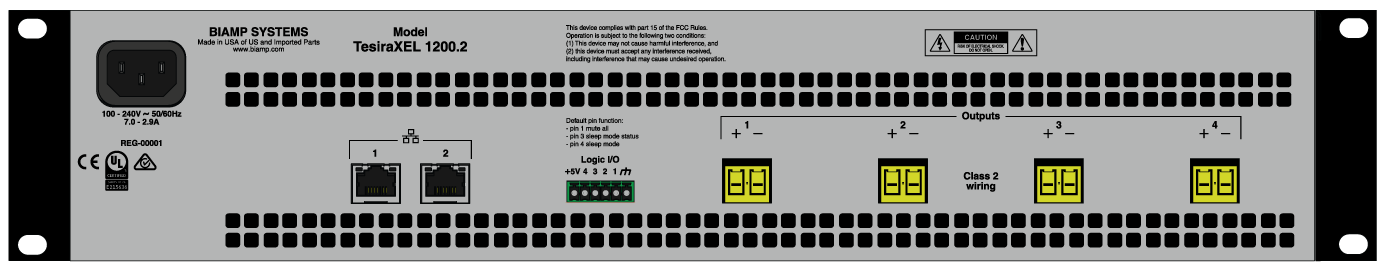
GPIO logic pin functions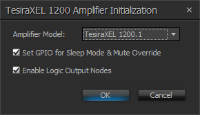
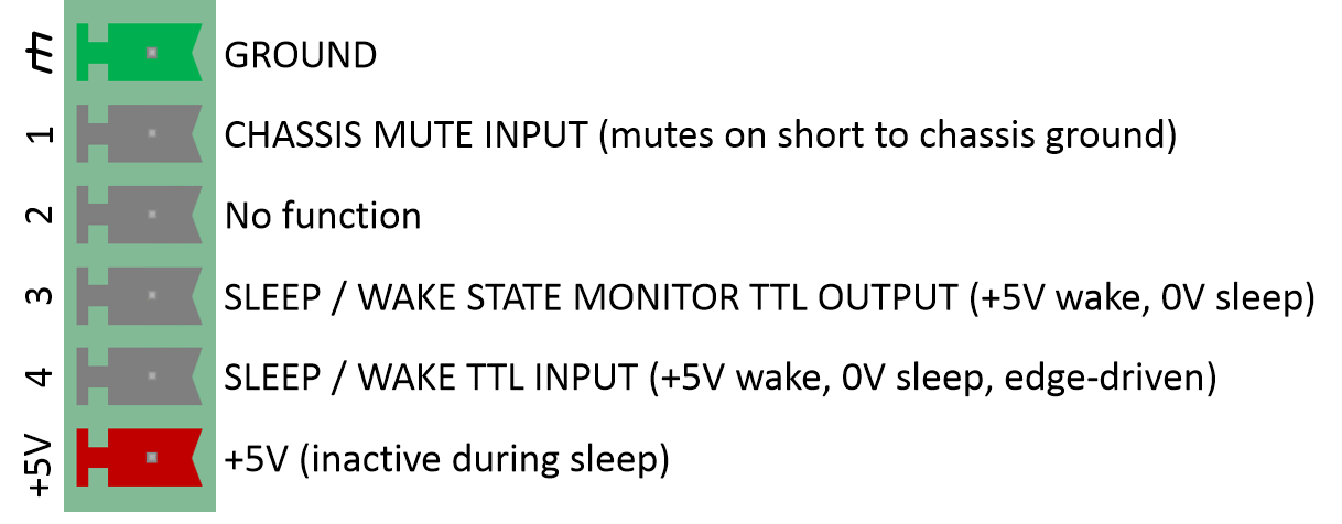
The TesiraXEL 1200 amplifier GPIO block has two optional functional states, which are configured via Tesira software:
- dedicated Sleep Mode & Mute Override (default mode)
- standard Tesira Server-class GPIO connector
The "Sleep Mode & Mute Override" checkbox is checked by default when adding an amplifier in Tesira software. It must be unchecked to enable standard GPIO function.
The GPIO mode may be changed only in the amplifier control block parameters while Tesira software is offline, either when first adding the DSP block to the file, or by right-clicking on the block and selecting "Edit block parameters." Use the "Chassis GPIO connector: Sleep Mode & Mute Override" checkbox to set the behavior. The configuration must be sent to the system to update this state.
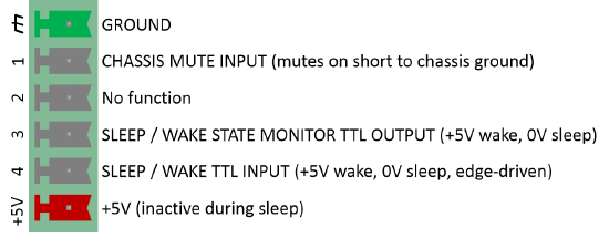
Remote Chassis Mute Override
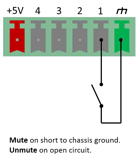
TesiraXEL 1200 series amplifiers feature a dedicated chassis mute GPIO connection on the rear panel. When GPIO pin 1 is shorted to ground, it will force a chassis-wide mute state. The GPIO remote mute overrides the software or front panel buttons' mute activities.
If GPIO pin 1 is left disconnected or in an open circuit, the input is open (floating) and the amp passes audio. An internal pull-up resistor pulls the floating input state to high.
If GPIO pin 1 is shorted to ground it is muted. Shorting to chassis ground pulls the logic state low.
When connected to a Tesira logic output, Logic High = Unmuted, Logic Low = Muted.
The contact closure and logic output methods can be implemented together by wiring them in parallel.
Active, remote chassis mute is indicated via front panel channel mute LEDs, and the channel mute and Mute All indicators in the amplifier's Dialog Block.
Remote chassis mute via GPIO pin 1 cannot be defeated in software.
Note: The remote chassis mute does not override the Audible Locate feature, which is typically only used in commissioning or troubleshooting a system. The Audible Locate feature plays a short voice message on each output channel in sequence and has an automatic time-out of 60 minutes.
Sleep Mode
The 1200 series amplifiers offer a low-power chassis Sleep mode. This mode can be triggered via the front panel "Sleep" power button or via the rear panel GPIO connector on pin 4. Sleep cannot be triggered by TTP command or via software, only by physical interaction with the GPIO or front panel.
Sleep state can be monitored via GPIO pin 3, which will output a TTL high while awake, and a TTL low while in sleep.
Sleep mode is mandated in some applications where a low power mode during system down times is required. In sleep mode, the TesiraXEL amplifier's current draw is reduced to 2.5W at 120V (allowing the logic IO and Sleep buttons to operate). For comparison, the 1200 amplifier in standby mode (all channels automuted) uses 51W, a TesiraFORTE uses 35W, and a Server-IO with a single DSP-2 card and an AVB-1 card draws 50W (all at 120V).
Sleep is effectively a power on/off for the amplifier chassis and its internal AVB switch. The internal AVB switch is powered down along with the amplifier modules. Prior to entering sleep mode, the amplifier notifies the Tesira system to prevent any false warnings for undiscoverable devices being thrown. The Tesira system tracks the sleep state of all configured amplifiers to prevent discovery errors on the Tesira network when they are offline. Other devices can report sleep status of an amplifier via the TTP queryDEVICE get discoveredServers
Sleep mode is not recommended if the amplifier is used as a daisy-chained device. While the chassis is in sleep mode, any connected downstream daisy-chained devices will be "hidden" from the network due to the powered-down switch. Amplifiers using sleep mode should only be connected directly to the control and AVB network.
Amplifiers can be put into and out of sleep mode using a physical link between pin 4 and ground of the TesiraXEL and the GPIO port of another Tesira device. TTL logic high/low states from the controlling device's ports will place the connected amplifier for sleep or wake modes. This provides a simple method of putting amplifiers into sleep without an external power management device.
Sleep and wake modes are triggered by 5-volt TTL edge-driven logic, allowing users to use logic in conjunction with the front panel button.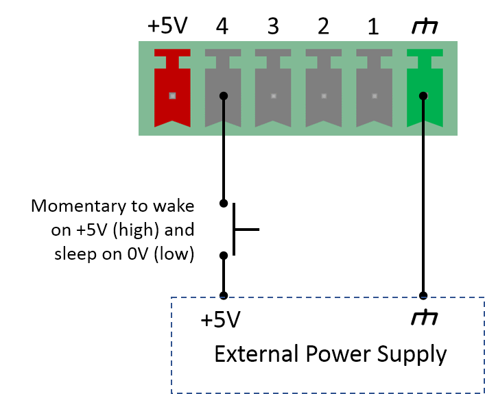
- While asleep (in a 0V state), a +5V pulse will wake the amplifier (the return to 0V is ignored).
- While awake, a +5V pulse and subsequent return to 0V will drive sleep mode.
- Pulse durations should be greater than 250ms.
Note: When amplifiers go into sleep mode, they are almost totally powered off (aside from the pin 4 IO connection and front panel sleep button functions) and become unavailable from the control network. The front panel Power LED will be lit, while all other LEDs will be dark. The total boot time from off or sleep mode is approximately 90 seconds. If the desired behavior is to simply enforce a hard mute of the amplifier from an external trigger then it may be preferable to use the dedicated mute (logic pin 1) rather than sleep (logic pin 4) for your application. This allows instantaneous signal recovery when the logic high is removed (no lag due to waking from power off state), and the amplifiers will not drop off of the control network; as the switch remains powered at all times, there is no need to rediscover the devices.
Expected Tesira software behavior using Sleep mode
After receiving a logic pulse via pin 4 or Sleep via the front panel and entering sleep mode GPIO pin 3 will immediately go low and audio will be muted within approximately 20 seconds. TesiraXEL 1200 amplifiers will send a notification to the Tesira system prior to entering sleep mode. This message will prevent errors and warnings that would otherwise be seen if a network device became unavailable. In daisy-chain configurations, there will be sufficient time to allow this message to propagate upstream through all other sleep-enabled hardware prior to the device's switch powering down. Upon waking, GPIO pin 3 will immediately go high and the amplifier will be passing audio and available for system commands within approximately 90 seconds.
The TTP command DEVICE get discoveredServers will show the state of the Tesira Server-class devices visible to the unit being queried. Only TesiraXEL are capable of sleep mode, so all other devices should always return a "sleeping":false status. A sleeping amplifier is effectively off, and its network ports are offline. A TTP message cannot be sent to a sleeping device, but all other devices in the same system will 'know' its sleep status and will return a "sleeping":true message as seen here:
DEVICE get discoveredServers
+OK "value":[{"ip":"169.254.141.131" "hostname":"Server-IO-02095938" "sleeping":false} {"ip":"169.254.252.252" "hostname":"13-CI-AVB-0570" "sleeping":false} {"ip":"169.254.60.242" "hostname":"TesiraXEL03749044" "sleeping":false} {"ip":"169.254.66.239" "hostname":"TesiraXEL03750473" "sleeping":true}]
When connecting to a system, or attempting to send a system configuration update to a system, all devices in the system must be configured and discoverable on the network.
A pop-up Incomplete System dialog will be displayed:
- If an amplifier is sleeping. This is a notification only and does not effect proper operation once connected.
- If expected hardware is undiscoverable on the network it will be shown on the list and will have a unit # assigned.
- If expected hardware is unconfigured (identifiable by a unit # = 0) it will be shown in the list.
Note that the 'Sleeping' checkbox only applies to TesiraXEL devices, other Tesira devices do not support sleep mode. Any devices in the list with an empty checkbox are either not discoverable on the network or are discoverable but are not configured. These conditions must be remedied for proper operation.

Expected Canvas software behavior using Sleep mode
If an amplifier using sleep mode is part of a Tesira system using Biamp Canvas software, the Biamp Canvas software will give a warning that a network device is unavailable the first time each amplifier sleeps. When the amplifier wakes again there is no associated message, and future sleep events should not trigger pop-up messages.
Control blocks for audio passing to the amplifiers should be hosted in the upstream AVB DSP device. The amplifier automute state can still be used to allow channels to enter and leave mute status, but mute states will not be seen in Canvas.
Users may trigger a Tesira logic state via a Biamp Canvas file to initiate a sleep or wake-from-sleep event for one or more amplifiers. It is possible to incorporate logic delays in the file to sequentially wake a series of amplifiers. If a set of amplifiers is daisy-chained and using sleep mode, it is recommended that the wake command be sequenced so the amplifier directly connected to the network wakes first, then the first daisy chain connection, then the second, and so on.
Network connections
The TesiraXEL 1200 amplifiers have two 1-Gigabit RJ-45 ports. Their properties and network setup options are detailed at TesiraXEL Amplifiers - Network Configurations
Speaker connections
The TesiraXEL 1200 amplifiers have four powered outputs for loudspeakers. These can be configured in software for use with 8-ohm, 4-ohm, 70V, and 100V speakers. Mating plugs are included with the amplifier and can be reordered using Biamp part #322.0431.900.
TesiraXEL amplifiers DO NOT support the bridging of output channels.