GPIO Logic I/O ports on Tesira Servers and TesiraFORTÉ
This article describes the properties of the Logic I/O pins on a TesiraFORTÉ, Server, and Server-IO.
Each TesiraFORTÉ, Server, and Server-IO Logic I/O pin can behave as a Logic Input, Logic Output, or Voltage Control point (identical to pins 13-16 on an EX-LOGIC expander).
These connections are also available on the Tesira Forte X, Tesira LUX, Tesira XEL, Tesira AMP 8x and 4x series amplifiers.
Logic I/O
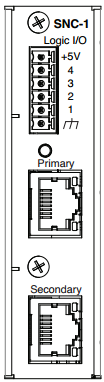 Located on the back panel of the TesiraFORTÉ, Server, and Server-IO, the Logic I/O connector block has a +5 volt pin, 4 logic/voltage control pins and a ground pin. It is labeled "Logic I/O". The functions of the 4 logic/voltage control pins are defined using Tesira software.
On a SERVER-IO or SERVER, the Logic I/O connector is located on the network card (SNC-1 or SNC-2). On a TesiraFORTÉ, the Logic I/O pin is located on the back of the device, to the left of the audio output connectors.
Logic inputs
A logic input can provide control of system actions like recalling presets, muting channels, ducking signals, combining rooms, etc by means of an external contact closure or 5V TTL logic. Shorting any logic input pin to the ground pin causes the corresponding logic input signal to go low, or off. Conversely, an open circuit (or a 5V TTL logic signal) causes the corresponding logic input to go high, or turn on.
Logic outputs
A logic output can be used to provide external indications such as lighting microphone LEDs or controlling external devices by using relays.
Logic outputs are “open collector” with an internal pull-up. This means that when not active, they will measure 5V but will not provide current. Upon activation (from a logic signal within the Tesira program), the logic output goes low, allowing current flow.
Note that if external power supplies of greater than 4V are utilized for LEDs (or other hardware), logic pins 1-4 may require the use of an external relay. To protect the analog-digital converter from over-voltage, there is a 40K Ohm resistor that diverts voltage greater than roughly 4V to the internal 3.3V rail.
If a relay is not used in conjunction with an external power supply on pins 1-4 an LED may remain in an on state, as the "leakage" current flowing through the resistor may be enough to partially power the LED. The exact voltage and current available to the LEDs will depend upon the external power supply and current-limiting resistors being utilized, and the intensity of the "leakage" on state is dependent on the LED efficiency.
Powered logic outputs
When configured as a logic output, each of the Logic I/O pins can optionally be configured as a current source to drive an LED directly (5V / 10mA maximum per output), without requiring an external power supply. When using TesiraFORTÉ, Server, and Server-IO as a power source, the corresponding Logic Output blocks in your Tesira configuration must be created with the "Enable Powered Outputs" option selected.
Voltage control
Logic I/O pins 1-4 are configurable to operate as variable voltage control connections. They can accept a variable input voltage (such as a potentiometer for volume control) up to 5V, this voltage can be sourced from the +5V pin (next to pin 4). The TesiraFORTÉ, Server, and Server-IO's analog inputs can be calibrated to the resistance range of a potentiometer that is connected to it via Tesira software. Potentiometers connected to Logic I/O ports 1-4 of the TesiraFORTÉ, Server, and Server-IO can be programmed in the software to control various system levels. When using the Logic I/O for Voltage control, the Tesira configuration must include a Voltage Control block. See Wiring potentiometers to the EX-LOGIC for further information.