TesiraXEL Amplifiers - Software and Discovery options
This article gives an overview of the software settings available for TesiraXEL amplifiers. It highlights which options are configured during offline setup versus runtime. It also discusses how faults are reported during runtime.
TesiraXEL amplifiers are server-class devices in the Tesira hardware family.
Getting connected
TesiraXEL is a server-class device. It is unique in the Tesira family in having 2 network ports which can operate as an AVB switch, passing data through to other devices.
In the default 'daisy chain mode' the units can be connected directly to a single Tesira Server / Server-IO or TesiraForte via the AVB port. When connecting one or more XEL to a standalone Forte or Server-IO the control PC must be connected to the TesiraXEL to allow communication through the chain to the DSP.
Important: In Tesira firmware version 3.12.0.15, RSTP must be enabled on the Port Mode tab of the Network Settings (Device Maintenance) for each amplifier to allow AVB to pass via Port 2.
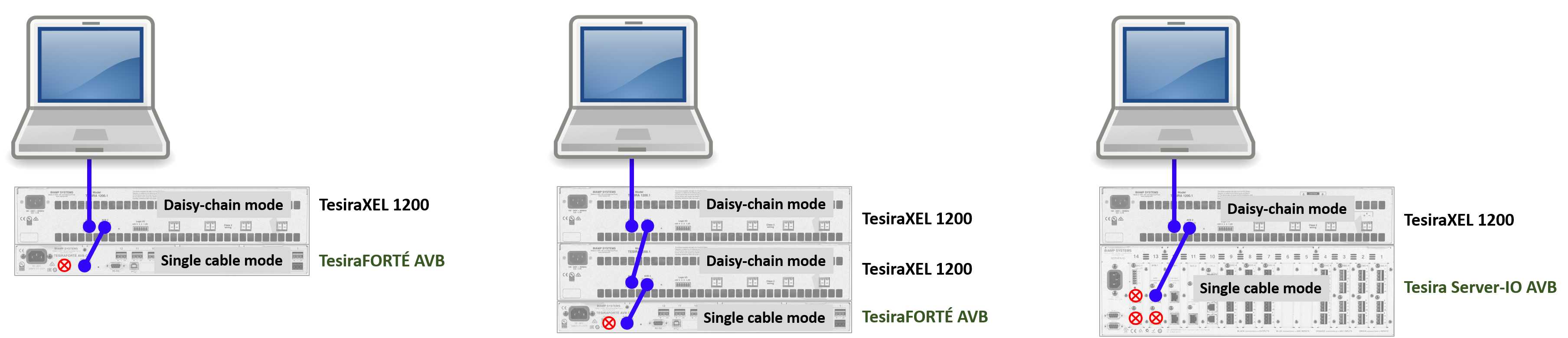
In the default 'daisy chain mode' TesiraXEL also supports a single cable uplink to an AVB network switch. The programming PC, control system, and other Tesira hardware can be connected to the switch for discovery and programming. The Server / Server-IO / Forte must be operating in single cable mode (connected only by the AVB port) in this application.
If a separated control network is desired TesiraXEL allows the use of 'Separate control and AVB networks' mode.
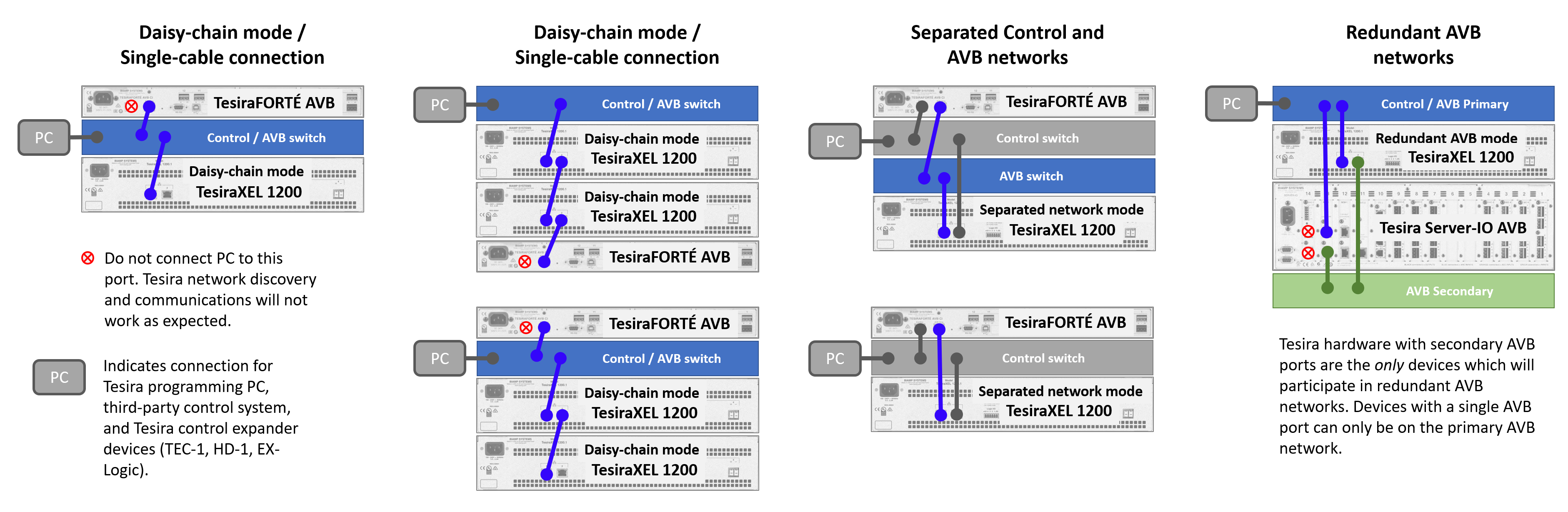
The Server / Server-IO / Forte cannot bridge network traffic across their Control and AVB ports for discovery, control, or AVB traffic. TesiraXEL can do all of those functions with its bridged network ports.
For expander-class devices Tesira translates and relays discovery, control, and configuration data via a server-class proxy host device. TesiraXEL is not a Tesira expander and as such cannot be discovered or communicated with across the control-to-AVB interface of Tesira Server-IO or TesiraForte.
Please refer to the article TesiraXEL Amplifiers - Network Configurations for further detail.
Options to set before compilation
Certain amplifier attributes are disabled in runtime to prevent accidental damage to components. They must be edited while offline and the configuration reloaded to hardware when changes are required. They are discussed in this section.
Setup tab 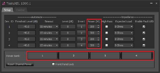
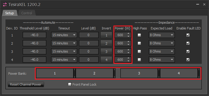
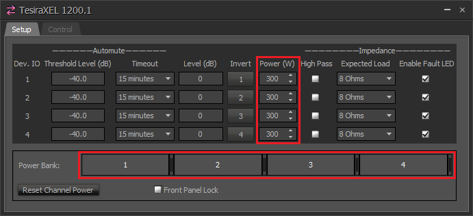
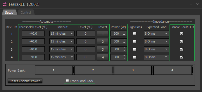
Power (W): Asymmetrical Power Bank settings
TesiraXEL 1200.1 and 1200.2 4-channel amplifiers feature an asymmetrical power bank architecture, allowing users to define how they choose to allocate the available power capacity between channels in 1W increments.
- The 1200.1 amplifier has a total chassis power of 1200W. The default setting of the 1200.1 is equal power on all 4 channels at 300W per channel.
- The 1200.2 amplifier has a total chassis power of 2400W. It houses two independent 1200W power banks. Each power bank allows asymmetrical power allocation across 2 channels. The default setting of the 1200.2 is equal power on all 4 channels at 600W per channel.
Power bank allocation is available for all channels. Power is defined in 1W steps: simply select whatever value you desire via the power bank slider handles or using the Power column spinner windows.
You must first "release" power from a channel to add power above the default values in other channels, the power bank slider will indicate free assets on the righthand side of the power bank window.
Level range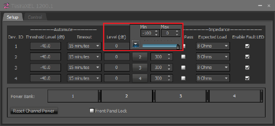

Upper and lower limits can be independently set on each channel's Level control range. The maximum and minimum levels defined here will be the upper and lower limits of the fader in the Control tab.
This feature is opened using the "up" arrow after clicking in the Level box. Values between 0 and -100 are allowed.
This Level state will be mirrored in the fader on the Control tab.
Impedance - Expected Load
Each amplifier channel is independently assignable in the Expected Load column as 4-ohm or 8-ohm (low-impedance) or 70V or 100V (constant voltage) capable.
The expected load defines an expected range for the amplifier to monitor its output voltage and current. If these diverge from the predicted healthy range then a warning may be shown or the signal attenuated.
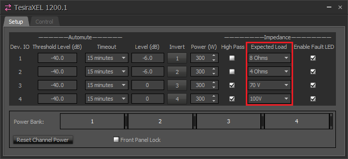 The amplifier does not require additional supply-side transformers for constant voltage applications. Biamp's high-performance, multi-channel amplifiers are capable of adapting their output voltage directly to low impedance speakers and constant-voltage speaker lines, without the need for output transformers. This method of transformerless interfacing is called Direct Drive.
The High Pass checkbox enables a 48dB/octave high pass filter with a -3dB cutoff at 70Hz. Disabling the checkbox moves the cutoff to 16Hz. It is also available in runtime. High Pass should typically be engaged when using 70V and 100V modes.
The Impedance Enable Fault LED checkbox enables impedance monitoring alerts on the channel indicators. Impedance values that are detected and considered outside of the expected nominal range for the expected load type will always show in the Error Logs for the system.
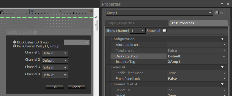 Delay Eq Groups
The 1200 series amplifiers offer the ability to use either a single Delay Eq Group for all outputs (default behavior) or allows users to define Delay Eq Group membership on a per-channel basis.
Using the per-channel option allows the Tesira software to apply the appropriate Delay Eq compensation for each output based on its location (e.g., 2 channels of the amplifier service Ballroom A, while 2 channels service Ballroom B across the hall. The two ballrooms do not share any audio sources, so do not need to belong to the same Delay Eq group. Giving each system its own Delay Eq group allows each system to have the lowest latency for its application).
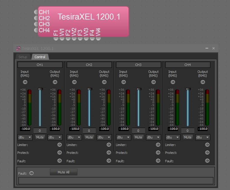
Settings are applied in the amplifier block's Properties sheet in Tesira software.
Settings available in runtime
 Some options are available during runtime. They are discussed in this section.
Setup tab
Signal Level and polarity Invert can be managed here. The Level control is mirrored in the Control tab.
Automute (Standby) Mode
The 1200 series amplifiers offer an automatic per-channel and chassis automute mode, commonly called "standby mode." It is disabled by default.
Users define two automute variables per channel: a minimum signal threshold and a minimum time since the last input above the threshold was detected. When both variables' conditions are met, the channel will go into standby mode, reducing the amplifier module power consumption to its minimum level.
Once all 4 input channels meet their respective standby criteria, the amplifier is in chassis standby.
- The timeout options are Disabled (meaning the channel will never enter standby mode), 15 minutes, 30 minutes, 45 minutes, and 1 hour.
- Any time a channel input signal exceeds the audio threshold the unit will instantly begin passing audio and the channel's standby timer will be reset.
Automute active status is indicated by a yellow LED on the front panel (per channel).
While in full chassis standby the amplifier is still visible on the control network, the internal switch is powered and active, and the unit will instantly begin passing audio once it exceeds the defined input threshold.
The amplifier will consume about 51W at 120V in full chassis standby (all 4 channels in automute). For comparison, a TesiraFORTÉ AVB uses 35W, and a Server-IO with a single DSP-2 card and an AVB-1 card draws 50W (all at 120V).
An upstream mute (in the DSP passing AVB to the amplifier) causing input signals to the amplifier to stop will result in the same power consumption behavior as standby mode.
Impedance - High Pass
When checked, the High Pass option engages a 70Hz high pass filter. When unchecked, the filter is moved to 16Hz. High pass should typically be engaged when using 70V and 100V modes.
Impedance - Enable Fault LED
The Enable Fault LED checkbox can be enabled and disabled in runtime. This option allows suppression of faults specifically related to impedance being out of the expected nominal range.
Control tab 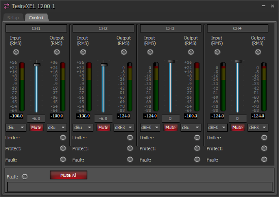
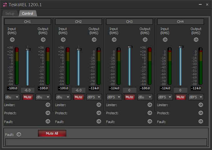
Output controls are available per channel during runtime.
Level
In the amplifier Control tab there is a Level control output fader. The control allows attenuation downward from unity. The level is mirrored in the Setup tab.
Mute
The channel mute buttons available here are physically mirrored on the amplifier front panel.
The Mute All button engages mute state on all channels. If any channel is unmuted, the Mute All state is defeated. Releasing Mute All unmutes all channels simultaneously. Muting all channels individually causes the Mute All button to illuminate.
Channel mute buttons and the Mute All button are illuminated while the amp is remotely muted via the rear panel GPIO connection. This cannot be overridden in software.
Channel mute state is also indicated by front panel LEDs.
Meters
RMS meters indicate audio input received into the amplifier, and the post-fader and post-mute output level.
RMS meters can each be optionally displayed in dBFS or dBu.
Note that the signal intensity is the same in both instances, but the notation describing it is changed. Tesira software indicates dBu levels as 28dB higher than dBFS, so that +28dBu = 0dBFS.
This is analogous to inches vs centimeters, miles per hour vs kilometers per hour, gallons vs liters, etc.
dBFS is commonly used to describe digital signals where 0dBFS is the digital clipping point. 0dBFS is referenced to peak level, not RMS.
Clip indicator LED
The clip LED will illuminate if consecutive input samples are interpreted as out-of-range or undefined (digitally clipping). This can occur if the AVB signal is not being properly limited before the hop to the amplifier.
Tesira's full-scale peak sine wave clipping point (0dBFS) is +28.0 dBu. RMS values for full-scale sine waves are 3dB lower than peak (.707).
Device fault reporting
 The 1200 series amplifiers use a scrolling banner within the amplifier's Control tab in Tesira software to display active faults in the amplifier.
The amplifier block's logic output nodes labeled F1-F4 (one node per channel) will present a logic low when no faults are present and a logic high if a major fault is present. A fault which is unique to a channel triggers the channel LED / logic.
The Fault activity light state in the software block matches the logic node and front panel fault LED state. Logic warning nodes labeled W1-W4 are also present, to report when a channel goes into a minor fault state. The scrolling banner in the amplifier block or the device's status in the system status will show the faults.
A list of possible fault messages is available in the Tesira Help file under Fault Reporting.
Sites using Biamp SageVue for systems monitoring can subscribe to the faults for real-time or time-based reports.
Channel impedance fault suppression 
The amplifier monitors the connected impedance and compares it to a nominal expected profile for the selected output impedance mode. If the measured impedance is out of range, a fault will be reported in the Event Logs and will be shown in the device faults.
Impedance faults are always logged in the Event Logs for the system.
Users can check the "Enable Fault LED" box in the setup tab to allow impedance faults to trigger the amplifier front panel Fault LED.
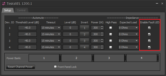 In some scenarios, a system may be operating normally, but the impedance load is outside of the expected "normal" window, triggering a fault. We provide a mechanism for suppressing Fault LED activity under these conditions.
If the "Enable Fault LED" checkbox is cleared, then impedance faults will not cause activity on the front panel LED. It also applies to the logic "F" node of the amplifier block.
| Enable Fault LED box unchecked |
If an impedance fault is detected in a channel with the Enable Fault LED box unchecked
|
| Enable Fault LED box checked |
If an impedance fault is detected in a channel with the Enable Fault LED box checked
|