TesiraXEL Amplifiers - Network Configurations
TesiraXEL is designed for use with Tesira DSP processors and requires at least 1 Tesira DSP to pass signal to the amplifier over AVB.
TesiraXEL 1200 amplifiers have two software configurable, AVB-capable network ports; this is a unique hardware layout in comparison to other Tesira hardware. This allows TesiraXEL amplifiers to perform as daisy-chained network devices, adding new network topologies to Tesira designs.
TesiraXEL offers the ability to daisy chain the network ports, use single cable mode per amplifier, or use redundant AVB ports for signal path resilience.
TesiraXEL ships with Daisy Chain / Single-cable mode enabled by default. Connect the PC via port 1 (left port) of the XEL amplifier for discovery. Port 1 will support discovery in any network mode.
Network connection examples
Standalone system
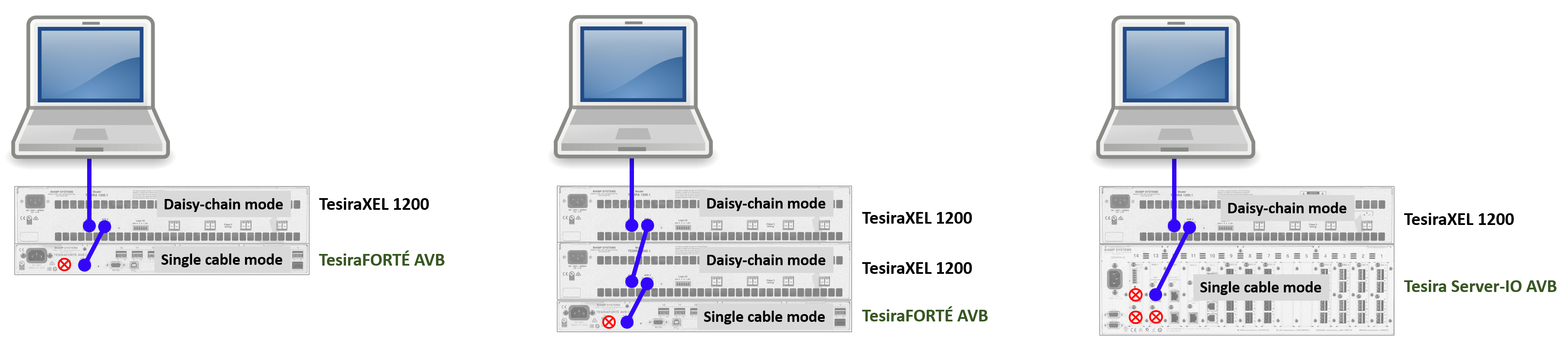
It is possible to have a very simple network of one Tesira DSP device plus one or more TesiraXEL amplifiers. No network port configuration is required but the devices must be wired properly to allow device discovery.
In this configuration the PC used for configuration must be connected to the TesiraXEL rather than the DSP hardware's Control port. TesiraXEL's internal switch forwards AVB, discovery, and control data to the DSP hardware's AVB port which is running in single-cable mode (when the Control network port is left disconnected, single cable mode is enabled automatically on the AVB port). TesiraForte and Server / Server-IO cannot pass server-class discovery and control data between their Control and AVB ports.
Important: In Tesira firmware version 3.12.0.15 and later, RSTP must be enabled on the Port Mode tab of the Network Settings (Device Maintenance) for each amplifier to allow AVB to pass via Port 2.
If a 3rd party control system will be connected over Ethernet then a control network switch can be placed where the PC is seen in the illustration, and the PC and 3rd party control processor can be connected to that switch.
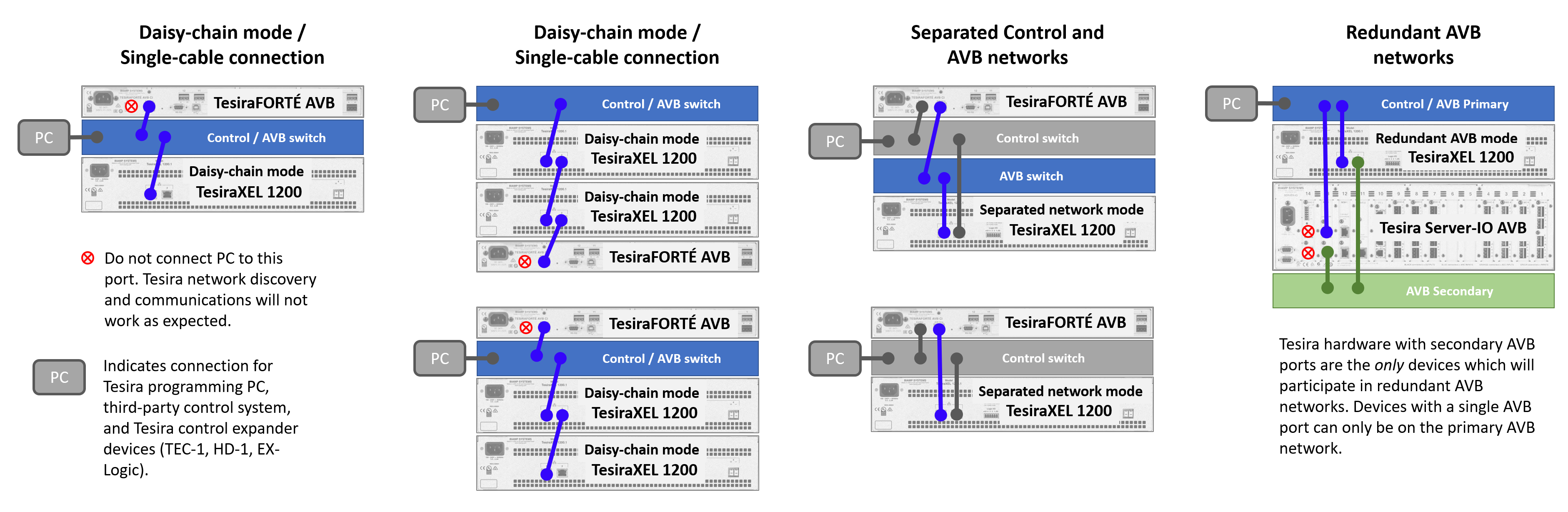
Basic network configurations
Below are some examples of the network configuration options available for TesiraXEL amplifiers. Tesira Server / Server-IO may be used where TesiraForte is indicated.
TesiraXEL ships with Daisy Chain / Single-cable mode enabled by default. Important: In Tesira firmware version 3.12.0.15 and later, RSTP must be enabled on the Port Mode tab of the Network Settings (Device Maintenance) for each amplifier to allow AVB to pass via Port 2.
Network port configuration
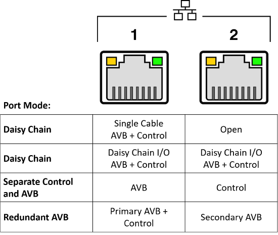
Port modes
The two TesiraXEL network ports support various configurations which affect their network properties. They can be configured for:
- Daisy Chain and single-cable mode: Control and AVB on both ports. Single-cable connection is supported on port 1 when port 2 is left disconnected. Daisy chain is initiated by connecting a TesiraXEL amplifier or Biamp DSP to port 2. (Amplifiers are in Daisy Chain mode by default. Important: In Tesira firmware version 3.12.0.15 and later, RSTP must be enabled on the Port Mode tab of the Network Settings (Device Maintenance) for each amplifier to allow AVB to pass via Port 2.)
- Separated Control and AVB: Control and AVB ports on isolated networks; port 1 = AVB, port 2 = Control.
- Redundant AVB: 1 = Control and AVB primary, and, 2 = AVB secondary. Control is only supported on the primary AVB network.
Port configurations can be changed by opening the amplifier's Device Maintenance window and navigating to Network Settings > Port Mode.
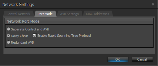
RSTP
The "Enable Rapid Spanning Tree Protocol" (RSTP) option is available in software / firmware 3.12 and later.
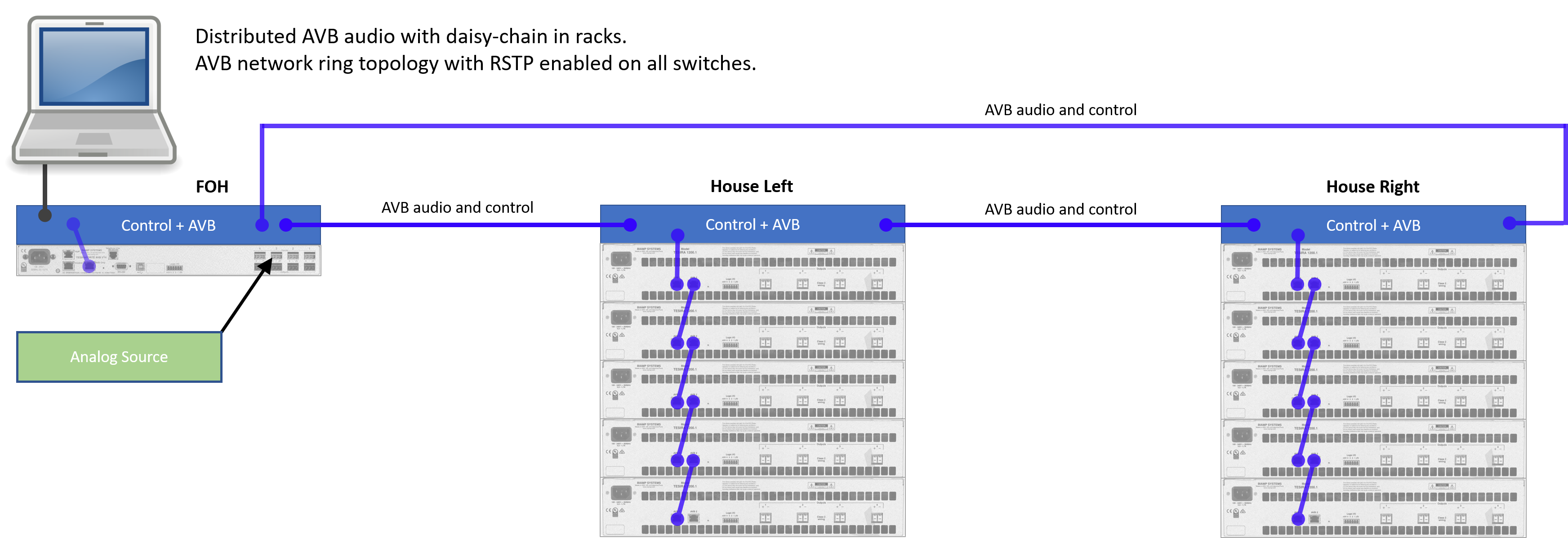
RSTP allows XEL amplifiers in Daisy Chain mode to be connected in a ring topology for network path redundancy in the event of a cable or port failure.
RSTP is an ethernet network protocol. In an STP or RSTP enabled environment if a network loop is detected one of the paths is elected as the primary path, and the other path is labeled as secondary and is disabled (to prevent broadcast storms). In the event a path failure occurs it affects the overall network topology. Reconfiguration of network paths by all participating switches may require a short time to execute, depending on the network architecture, and AVB playout may halt while it is reconfiguring.
MAC addresses
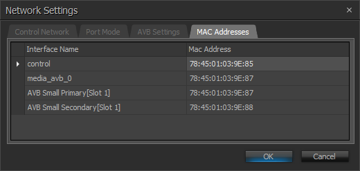
When the amplifier is in Daisy Chain or Redundant AVB mode the control data is shared on AVB port 1. In Separate Control and AVB mode a dedicated Control port is enabled on port 2. This is reflected in the MAC address list shown for the device in each mode.
|
Daisy Chain and Redundant AVB modes |
Separate Control and AVB |
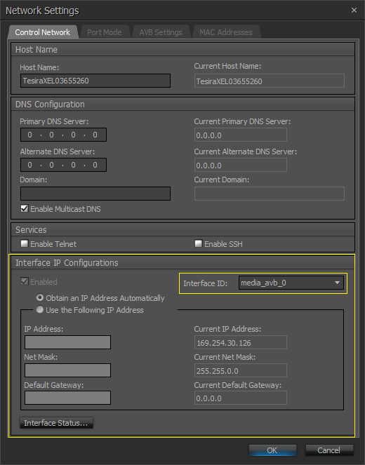
IP addresses are assigned in the Device Maintenance > Control Network tab. IP addresses can be assigned manually, automatically via DHCP, or automatically negotiated using APIPA for control and media_avb_0. They must be in unique address subdomains. In single cable / daisy chain and redundant AVB modes the control interface is disabled. |
|
|
|
|
When Daisy Chain or Redundant AVB network port modes are enabled Interface ID media_avb_0 is seen in the Device Maintenance > Control Network tab. |
When Separate Control and AVB network port mode is enabled Interface ID properties for control and media_avb_0 are seen in the Device Maintenance > Control Network tab . |

802.1X security
Tesira XEL supports 802.1X port security for the control and AVB interfaces. 802.1X protocol uses a central managed membership list to grant network access only to hardware devices which can provide proper authentication.
802.1X does not work on dynamic AVB VLANs on Extreme Networks hardware. If 802.1X is desired on AVB an alternate AVB VLAN can be manually created and 802.1X enabled.
Please refer to the Biamp Cornerstone article on 802.1X for more details.
Supported network modes
When the device is not in daisy-chain mode, the internal AVB switch is disabled. The two network ports are logically separated in the amplifier and do not belong to a common network domain. This allows different network design topologies to be supported.
Port configurations can be changed by opening the amplifier's Device Maintenance window and navigating to Network Settings > Port Mode.
Daisy-chain mode and single-cable mode (default mode)
TesiraXEL 1200 series amplifiers ship from Biamp's factory in "Daisy Chain" mode by default, supporting a combined Control and AVB network connection. The second port provides Control and AVB pass-through for other Tesira devices. When port #2 is left disconnected, the amplifier functions in single-cable mode for the network. Note that any TesiraXEL amplifier at the very end of a daisy-chain stack is in a single-cable condition and must be connected using port 1.
- Port 1 should always be used for connection to the network switch when using single-cable mode or in daisy-chain mode, and for the amp located at the end of a daisy chain
- Ports 1 and 2 support bi-directional daisy-chain I/O within a daisy chain
Daisy-chain mode allows one network connection to the stack. If a second, non-Biamp connection is detected with one or more amplifiers in daisy-chain mode, a warning will be shown and the second link will be deactivated to prevent broadcast storms or bridged networks. The TesiraXEL amplifier in daisy-chain mode is not intended as a bridge between other switches.
The two ports are linked by an internal, unmanaged AVB pass-through switch (network bridge), allowing multiple amplifiers to be connected together in a daisy-chain fashion.
Important: In Tesira firmware version 3.12.0.15 and later, RSTP must be enabled on the Port Mode tab of the Network Settings (Device Maintenance) for each amplifier to allow AVB to pass via Port 2.
Amplifiers in daisy-chain mode use AVB. Daisy-chaining is an added network topology choice, and does not limit your ability to route signals to amplifiers in any way.
Separated Control and AVB networks
The 1200 series amplifiers support separated control and AVB network topologies, requiring each port to be connected to a unique network domain. This allows users who want to physically isolate AVB traffic from the control network to do so.
Daisy chain mode is not supported for the separated networks topology, as this would cause the amplifier's internal switch to bridge the two networks.
In separated networks mode, port 1 is the AVB port and port 2 becomes the Control port.
Redundant AVB networks
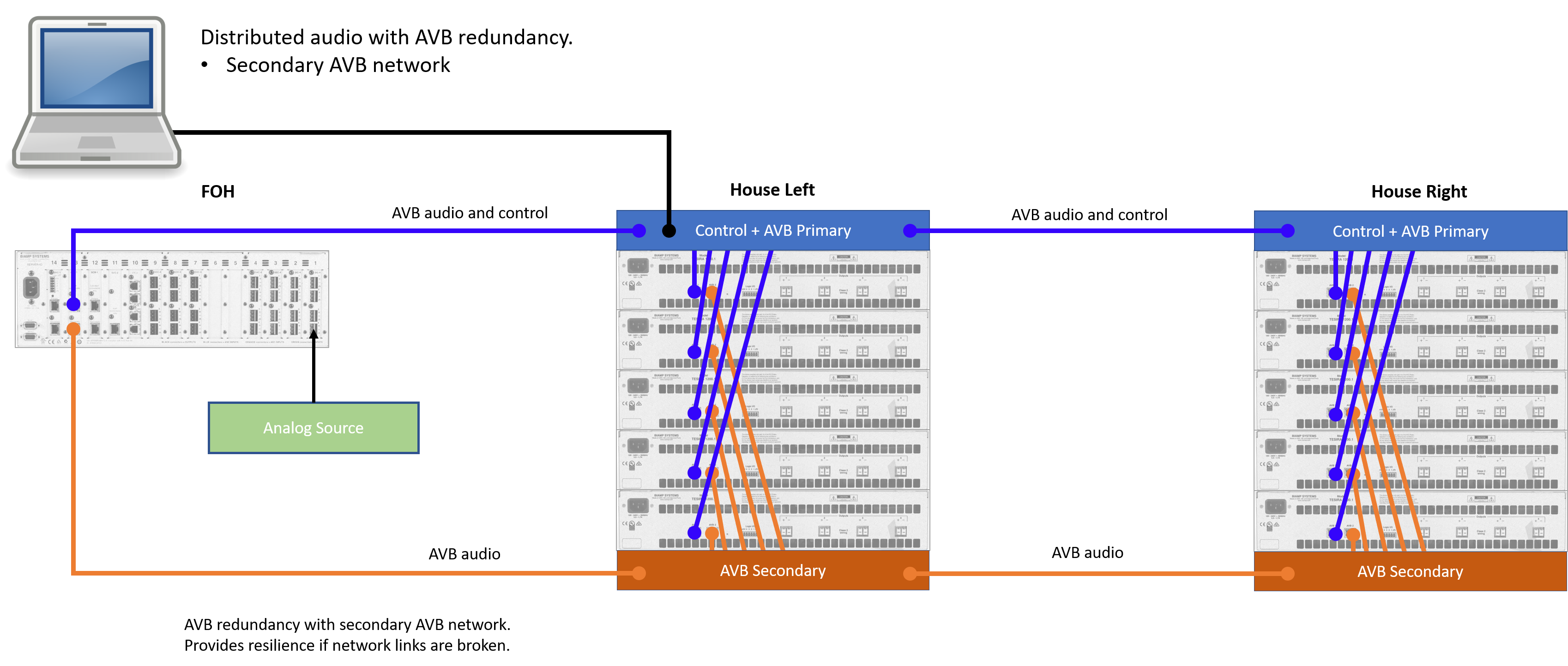
The 1200 series amplifiers support redundant AVB networks as provided by Tesira Server and Server-IO AVB-1 cards. In this scenario, the Primary and Secondary AVB networks should be in separate network domains. Unique, redundant AVB streams are maintained at all times on both networks.
- A failure on the Primary AVB network will immediately cause AVB audio from the Secondary AVB network to be used by all AVB stream listeners if it is still available.
- If a Talker device fails altogether, or does not have an AVB Secondary port (such as a TesiraFORTÉ), then audio cannot fail over to the Secondary network.
- Restoration of the Primary AVB network will then allow it to function as the failover for the Secondary AVB network as needed.
Control data is only supported on the Primary AVB network at this time. In the event of failover to the redundant Secondary AVB network, the device will be undiscoverable in Tesira software and a discovery fault will be shown in the system; control data will not pass to the affected device(s).
AVB redundancy requires all participating devices to have both primary and secondary AVB ports. Only Tesira Server, Server-IO, TesiraXEL, and TesiraAMP support AVB redundancy. Devices with a single AVB port can only share audio across the AVB primary network.
In redundant AVB networks mode, port 1 is the Control and AVB Primary port and port 2 becomes the AVB Secondary port.
Adding a ring to the switch network increases resilience. Changes to the network may cause short outages while the network reconverges. RSTP should be enabled on all switches to prevent broadcast storms.

Daisy-chain topologies
Signal path resilience
Signal path best practices are discussed in the article TesiraXEL amplifiers - Signal path redundancy concepts
Each amplifier channel is a unique output
Daisy-chaining does not limit your ability to route unique signals to any amplifier output channel, no matter where it resides in the daisy-chain stack. Signal paths are defined in Tesira software.
Any amplifier chassis may receive up to 4 channels of audio from up to 4 AVB streams. Signal routing may also be mirrored (fanned out) across multiple devices, regardless of participation in a daisy-chained network topology.
End-of-chain Tesira DSP devices
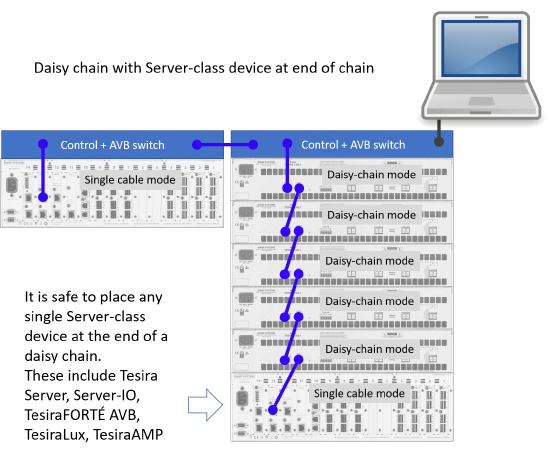
If multiple Tesira server-class devices (Tesira Server, Server-IO, or TesiraFORTÉ) are in a system, one may be placed at the end of a TesiraXEL amplifier daisy-chain stack. The end-of-chain server-class device must use single-cable mode. Only Server-class devices are allowed at the end of a daisy-chain (Server, Server-IO, TesiraFORTÉ, TesiraLux, or TesiraAMP)
Important: In Tesira firmware version 3.12.0.15, RSTP must be enabled on the Port Mode tab of the Network Settings (Device Maintenance) for each amplifier to allow AVB to pass via Port 2.
Tesira Server, Server-IO, TesiraFORTÉ, TesiraAMP, and other Tesira hardware with multiple network ports do not offer daisy-chain throughput capability due to different hardware architecture.
Using single-cable connection mode, one Tesira Server-class device can be placed at the tail of an amplifier daisy chain; in that case, the control PC and other third-party control system hardware must be connected at the opposite end of the daisy-chain to "see" all of the connected hardware. If a third-party control system over IP is used, then a control network switch is recommended.
If Tesira DSP hardware is positioned at the end of a daisy-chain, then the use of the TesiraXEL's sleep function is strongly discouraged. If the mid-span, daisy-chained amplifiers are put into sleep mode (switches powered down), then the end-of-chain DSP device will not be visible (or discoverable) from the network. Sleep mode should not be used in this configuration.
- The Server / Server-IO do not support daisy-chain pass-through between the Primary and Secondary ports of the AVB-1 card.
- The Server / Server-IO / TesiraFORTÉ do not support daisy-chain pass-through between the Control and AVB ports of the unit.
- It is not possible to put Tesira Server / Server-IO or TesiraFORTÉ at the "top" of a daisy-chain stack, as a bridge between the PC and the first TesiraXEL. They do not support daisy-chain pass-through from Control to AVB ports. Tesira device discovery will not function properly for connected devices.
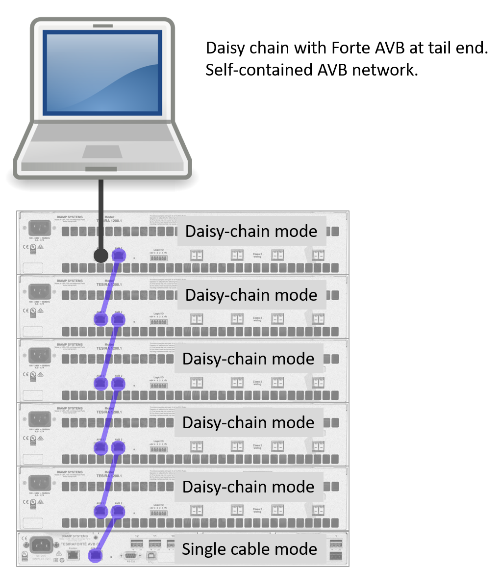
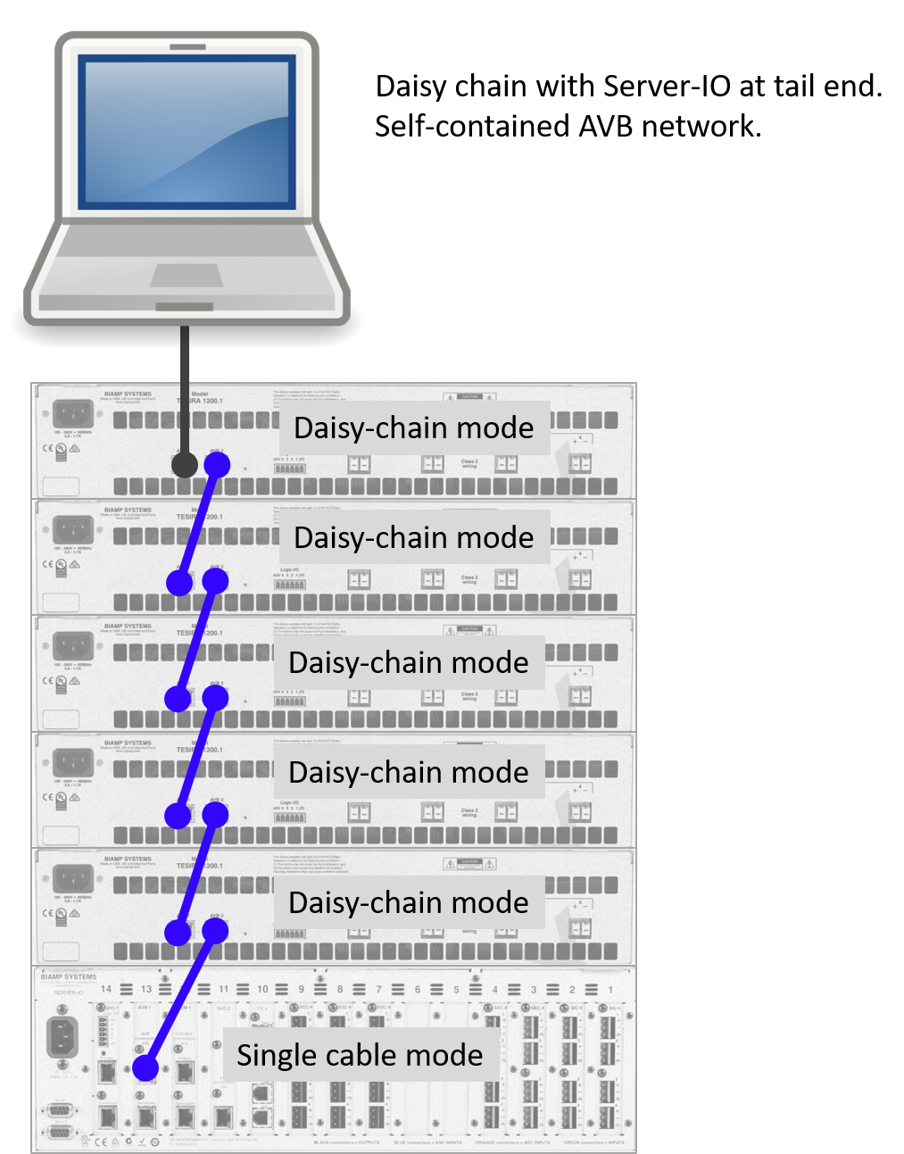
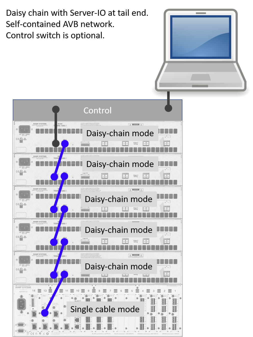
Self-contained AVB network
A self-contained AVB network (i.e., one without a third-party AVB switch) can be created by placing a single Server / Server-IO or TesiraFORTÉ at the end of a daisy-chain. When a host PC is connected at the opposite end of the daisy chain, Tesira discovery and AVB will work as expected. A control switch is optional. The end of chain Server / Server-IO or TesiraFORTÉ must use single-cable mode. This topology creates a self-contained AVB network.
*** If a Server / Server-IO or TesiraFORTÉ is placed between the PC and the first TesiraXEL then the amps will be undiscoverable from the PC. Those devices do not bridge their control and AVB ports. The PC must be connected to port 1 of the TesiraXEL and the Server / Server-IO or TesiraFORTÉ connected to port 2 of the last device in the daisy chain.
Important: In Tesira firmware version 3.12.0.15, RSTP must be enabled on the Port Mode tab of the Network Settings (Device Maintenance) for each amplifier to allow AVB to pass via Port 2.

Multiple Daisy-Chain Racks
Daisy-chain mode is a powerful tool when implemented for smaller, local AVB networks, where AVB pass-through can reduce AVB network switch requirements. Be sure to consider our article on signal path resilience when designing your network.
A simple, single daisy chain through all amplifiers becomes limited by the total number of hops accrued along the path.
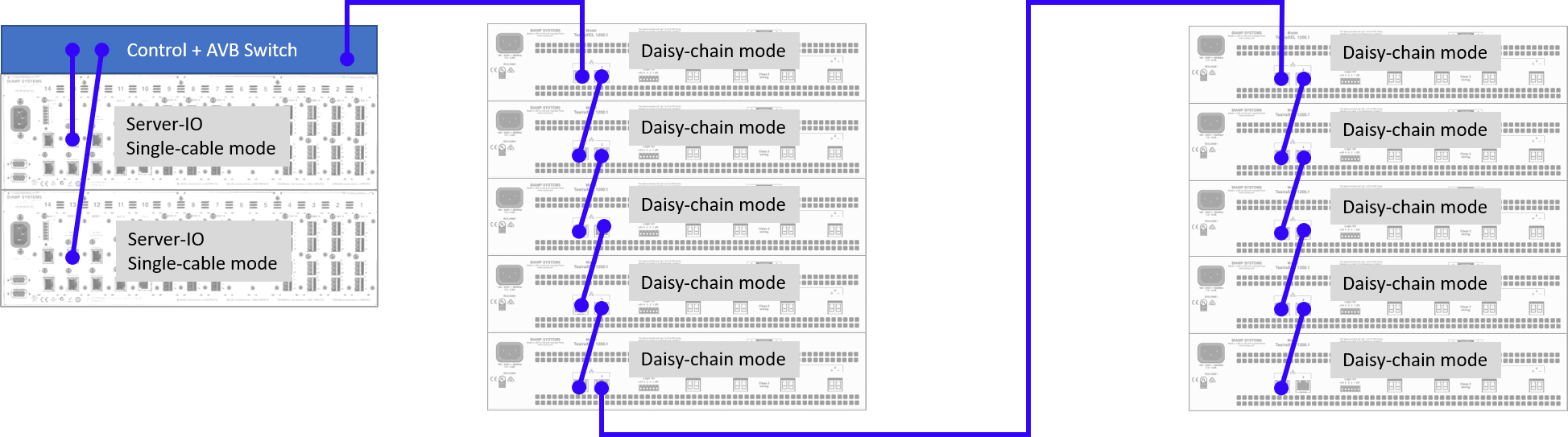
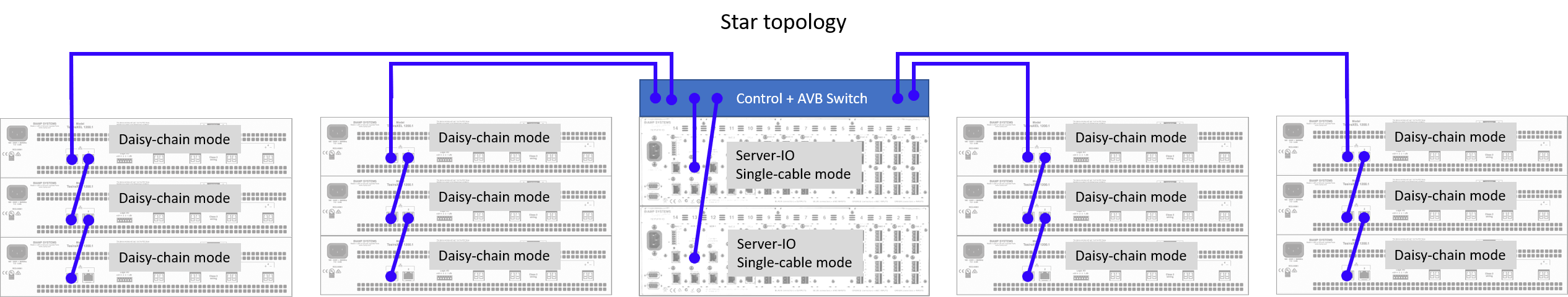
A star network topology may be used with multiple daisy chain racks to keep the overall network diameter in check. Limiting each daisy-chain stack to 4 or fewer devices will allow reasonable latitude with respect to network design and multiple switch tiers.(core and edge switches).
A stack of daisy-chained devices expands the overall AVB network diameter. The depth of the permitted daisy-chain stack is dependent on the overall AVB network topology. Latency through the TesiraXEL is known and we are comfortable implementing a 10-hop limit when daisy-chaining devices. (The recommended hop limit may vary depending on the network topology but will never be less than 9 hops.)
- A hop consists of one direct network link between two hardware devices.
- AVB network diameter refers to the number of hops along the longest path between any 2 devices in the Tesira AVB network.
- The TesiraXEL in daisy-chain mode is not intended as a bridge between other switches.
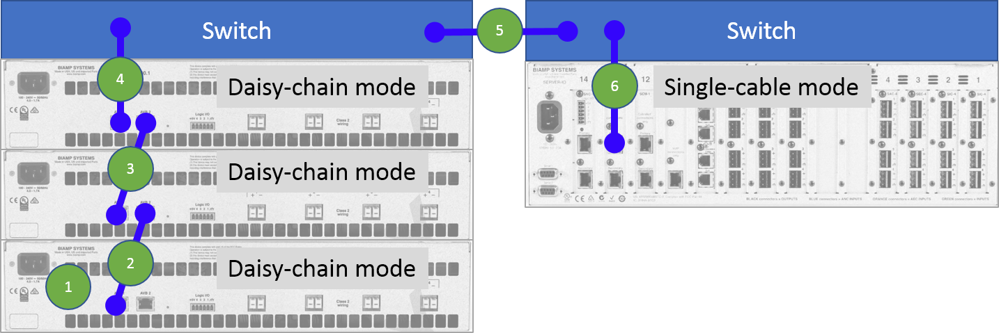
Notice that the image below counts hop #1 inside the bottom amplifier chassis, then counts the cable link between amplifiers as hop #2. This example shows 6 network hops between edges.
Note: Only TesiraXEL amplifiers support daisy chain mode.
End of chain device
The TesiraXEL amplifier has an internal AVB pass-through switch, which is active when "Daisy Chain" mode is enabled, this switch represents one network hop which must be added to the network diameter for the end-of-chain amplifier. For amplifiers in the middle of the daisy chain, the internal hop to the amplifier is not counted as it does not incur a cost against the overall network diameter. The last device in the daisy chain should be connected using port 1, and port 2 should remain open.
RSTP
RSTP allows the last port on the daisy chain to be looped back to the head end switch to create a secondary path in the event the primary path is interrrupted, This can be a powerful tool for managing risk tolerance.

AVB Network Diameter
A network hop is a link between two networked devices.
Biamp recommends a maximum AVB network diameter of 9 hops in order to guarantee that 2ms deterministic latency is maintained.
AVB networks that consist of purely gigabit-capable devices may allow the maximum network diameter to be 9 or more hops while maintaining 2ms deterministic latency. The total latency will be dependent on numerous variables including switch models being used and the firmware they are running, network size and topology, and the total number of AVB streams and AVB devices on the network.
Every network device has a pass-through latency, including AVB talker and listener endpoints and copper or fiber links and converters. The sum of all latencies must be less than 2ms to guarantee the ability to maintain playout synchronization across all endpoints at 2ms (2,000µs). The path from talker to listener must be under 2ms for all talker-listener paths in the system.
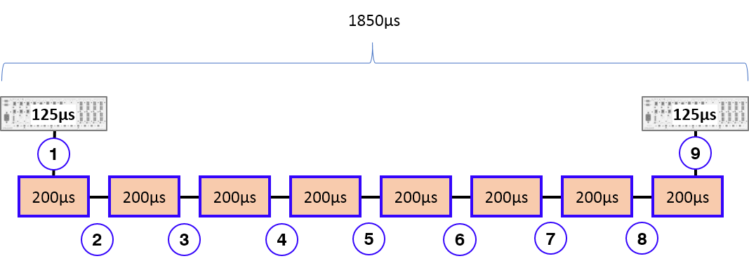
Biamp AVB endpoints incur 125µs latency per source and sink device.
Pass-through latency on switch hardware varies from 125µs to 200µs per device. Because the exact latency is unknown, we assume the worst-case scenario of 200µs across all network hops. Eight network switches at 200µs each, plus two endpoints at 125µs each totals 1850µs, leaving 150µs to spare. A daisy-chained system with 10 network devices requires 9 connecting links or "hops." This is how we determine the 9-hop maximum diameter.
A network comprised only of devices with a 125µs pass-through latency would allow a theoretical maximum of 15 hops while respecting the 2ms cumulative latency.
In practice, most networks end up with a blend of network device latencies. Some hardware has 125µs pass-through, while other devices may be 150µs pass-through, and others may be 200µs pass-through. Fiber converters may add considerable latency to a hop. This should be taken into account when designing the network and may allow for flexibility in the hop limit that is chosen.
In networks with a star topology, the overall network diameter must be calculated between the two farthest-apart AVB devices in the daisy chain.
It is generally recommended that no more than 9 hops exist between the furthest edges of the AVB network when using a 1G network. Larger diameters may be supported if throughput latency is known, but 9 hops is a conservative value that should always guarantee robust operation.