Getting Started with VenueTune
This article provides an initial overview of Biamp's VenueTune software and complements the Getting Started section of the VenueTune help. Information on the network configuration and supported topologies is also provided with links to the appropriate sections of VenueTune's online help system.
Please note: This article refers to "Voltera D" to include both the D and D M variants. D and D M amplifiers are functionally the same from a network standpoint. The Voltera D M differs in that it includes the full performance of a standalone DSP on top of the loudspeaker processing already included with the D models.
Minimum recommended SW version: VenueTune v2.1.2 (available from Biamp.com/downloads)
Supported FW version for VenueTune v2.1.2: Tesira FW v5.5.1
Opening options
A list of options is presented after VenueTune is launched. In this example, we are selecting New Project.

Establish Network Settings
The first step in designing and deploying a VenueTune project is to define the network configuration and settings needed. Network Settings can be accessed from the top left collapsible menu.

The Network Settings menu has two options:
- Adapter Settings
- Device Settings
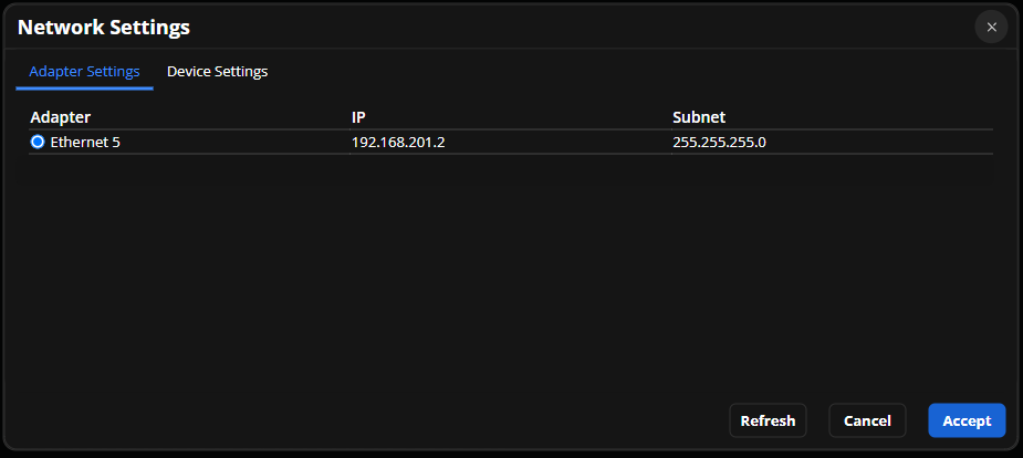
Adapter Settings
Under Adapter Settings, select the PC's network interface that VenueTune will use to communicate with Voltera D.
Device Settings
The Device Settings tab is used to select between DHCP or Static IP addressing and to configure the Port Mode settings for the Voltera D system.
Control IP Settings

If DHCP or APIPA is intended, then no other IP address consideration would need to be made within VenueTune.
If static IP is required for the control interface, then selecting the Static IP radio button provides a dialog to enter the Subnet and Gateway information shared by all Voltera D units that will be part of this configuration. Entering a gateway address is required. 0.0.0.0 may be entered if one is not desired for the network.
The static IP addresses for each Voltera D will be added later, during the Design Phase, when Amplifiers are added to the configuration.
VenueTune supports DHCP, APIPA, or static address assignment of the Voltera D control interface. The Dante interface supports DHCP or APIPA assignment. Static IP address assignment is not available for the Dante interface.

Port Modes
There are 3 port modes supported by Voltera D.
Default
Dedicated Control and Dante. In this port mode, P1 hosts the control interface and P2 hosts the primary Dante interface.


Converged
Converged Control and Dante. In this port mode, P1 hosts the control and primary Dante interfaces. P2 should remain link down.


Redundant
Converged Control and primary Dante with secondary Dante. In this port mode, P1 hosts the control and primary Dante interfaces. P2 hosts the secondary Dante interface.


Add Virtual Devices to the System
Once the network settings are defined, it is time to start adding virtual devices to the workspace.
Loudspeakers

Adding loudspeakers is managed in the Design Phase, Speakers Action.
-
Select the Design Phase
-
Select the Speakers Action
-
Add (+) speakers to the workspace

- Select the Biamp loudspeaker from the ALAMOS Library.
-
Increasing the Parallel quantity will define multiple loudspeakers for a single channel.
-
Selecting Create will add the loudspeaker(s) to the workspace.


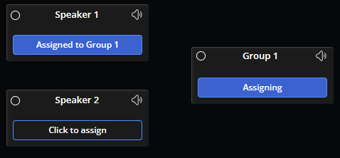
Groups

Grouping loudspeakers is managed in the Design Phase, Groups Action. Groups can be used to gather loudspeakers under shared overarching settings to design, tune, and configure a system in VenueTune.
-
Select the Groups Action
-
Add Groups to the workspace

- Assign the number of speakers to each group.
- This process and related features are detailed further in the Groups section of the VenueTune help file.
Amplifiers

Adding amplifiers to the workspace is managed in the Design Phase, Amplifiers Action.
-
Select the Amplifiers Action
-
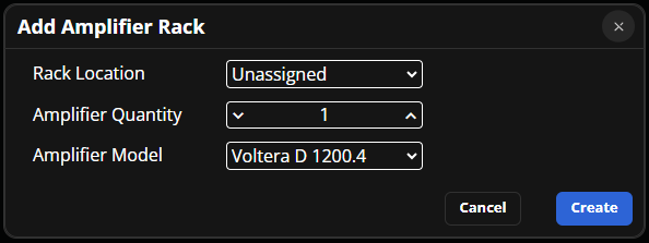
Add Amplifier Racks and the Amplifiers in them to the workspace

-
Choose or create a location for the amplifier rack. This is an optional organizational tool. See the Locations section of the help file, under Workspaces - Menus, for additional details about using locations.
-
Choose the amplifier model, then select Create to add it to the Rack.

- Other amplifiers can be added to an existing rack.
-
Select the '+' icon in the top right corner of the rack block.
-
Choose the intended amplifier mode and select Add.


Match and Link Virtual and Physical Devices
Match
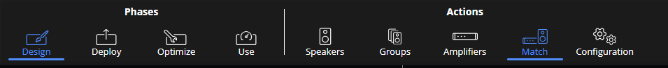
Once virtual devices have been placed, match the speakers with the amplifiers and link the virtual representations to physical devices connected to the system. Matching speakers to amplifiers is done in the Design Phase, Match Action.
-
Select the Match Action
-
Match the speakers with amplifier channels

When selecting the Match button on a speaker, the button will turn blue, and each available amplifier channel will be highlighted with a ring of color. (green in the above example).
Only the first channel on an amplifier in order may be matched with a speaker. For example, channel 2 is only available if channel 1 is already matched with a speaker, and channel 3 is only available after both 1 and 2 have been matched, and so on.
Once matched, the loudspeaker will reflect the amplifier name and channel it has been matched to.
Link

Linking virtual devices in the workspace to physical hardware discovered on the network is done in the Deploy Phase, Link Action.
-
Select the Deploy Phase
-
Select the Link Action
-
Toggle the network switch to the "Online" state


-
Link each virtual amplifier with a physical device from the list.
Once set to Online, VenueTune software will reach out and discover all Voltera D devices on the local subnet. In this example, two Voltera D units are discovered.
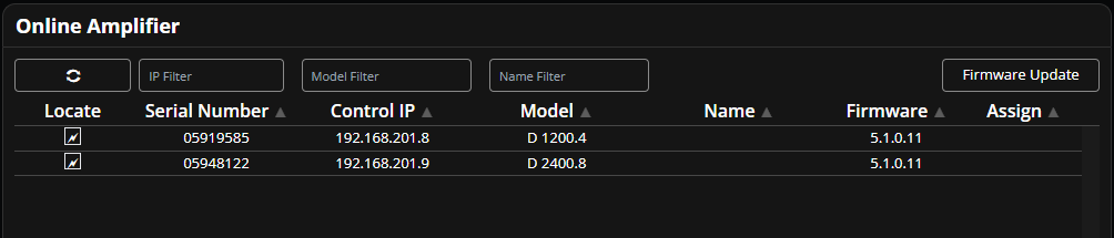
Selecting Link on one of the virtual amplifiers will automatically filter the discovered list down to compatible hardware.

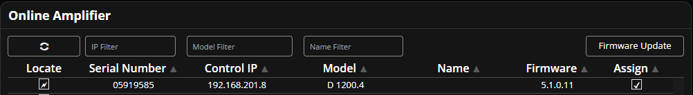
Once the Link button is selected on an amplifier, select a device from the list displayed in the panel to associate the selected virtual device with the listed connected physical device. This may take a few moments if IP address or port mode settings have been changed.


Once linked, a checkmark will be visible in the Assign column next to the selected hardware.
Input management and failover
When configuring Voltera D from VenueTune, local analog inputs are specific to the device they are connected to. Failover from digital to analog input is available, and inputs can be manually toggled between digital or analog sources for each loudspeaker channel. Please see the Input section of the VenueTune help system for additional information.
Loss of digital media on any channel will trigger failover for all channels. Dante failover is detected when a loss of a link to the media network is detected, or loss of the Dante subscription. The indicator to the left of the channel's source type will highlight to indicate whether Digital or Analog is the current active source.
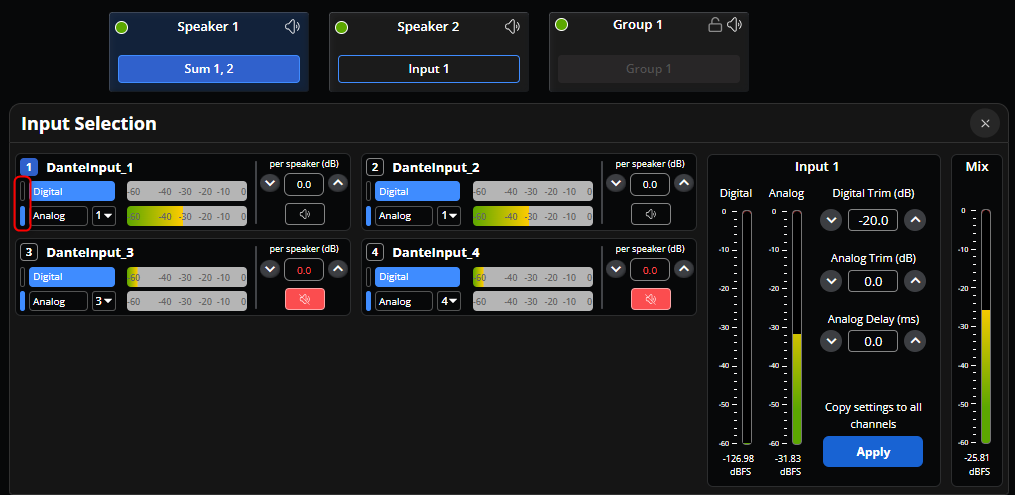
Pre Dante Failover
Channels 1-2 are receiving audio over Dante, with a backup analog source connected to input 1 of the Voltera D.

Both channels are configured to failover to analog input 1 using the analog routing drop down.

Post Dante Failover
Voltera D detects a loss of Dante flow and fails over to the defined analog input.
Factory Reset
Voltera D amplifiers ship ready for VenueTune and run a fixed layout file that VenueTune modifies based on the configurations made in each phase and action. If a Voltera D has previously been configured as part of a Tesira system, it can be reverted to using VenueTune by running a factory reset.
Each Voltera D has a recessed reset button on the rear of the unit.
-
First, locate the analog input ports on the rear of the unit.
-
Next, locate the small hole approximately 1/4-inch (0.6 cm) to the right of the analog inputs. The reset button is recessed just inside.
-
Find a suitable tool to insert into the hole and gently push the button - you should feel a small click as the button depresses slightly.
-
Press and hold the reset button for at least 10 seconds and then release. The reset process will begin after a few moments.
This reverts Voltera D to running the default VenueTune configuration.