Connecting a Shure MX396 to an EX-LOGIC
One popular application for the EX-LOGIC is to interface with conferencing microphones that feature mute switches and LED indicators, and Shure is a leading manufacturer of such microphones. This article describes how to physically connect a Shure MX396 microphone to a Tesira EX-LOGIC.
Note that even though this article shows diagrams for only the EX-LOGIC, the logic I/O terminals that are built into Tesira servers and TesiraFORTÉs can be used for the same purposes as an EX-LOGIC.
Goal
After completing the steps in this article, you will be able to connect a Shure MX396 to a Tesira EX-LOGIC. This will allow your Tesira configuration to control the LED's on the MX396, and it will also allow the mic's mute switch to control functions within your Tesira configuration (like mic muting).
Note that Shure MX series microphones use phantom power to power its LED's. Therefore, no external power supply is required for this application.
Conductor colors
The Shure MX396 is a multi-element boundary microphone with a mute switch and a bi-color LED. The MX396 comes with a unterminated cable containing all audio and logic conductors. The conductor color code for this cable is as follows:
| Conductor Color | Function |
|---|---|
| White | Audio 1 + |
| Green | Audio 1 - |
| Orange | Audio 2 + |
| Blue | Audio 2 - |
| Yellow | Audio 3 + (TRI models only) |
| Gray | Audio 3 - (TRI models only) |
| Shield | Audio ground |
| Black | LED In |
| Red | Switch contact |
| Silver (non-insulated) | Logic ground |
Wiring
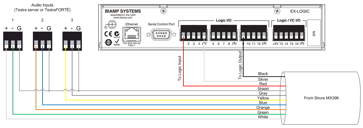
The audio conductors on the microphone will connect to audio inputs on the Tesira device like a typical microphone. Note that each capsule on the microphone requires its own dedicated input, so the MX396 will use two or three inputs per microphone (depending on whether the mic is a DUAL or TRI model). The LED and switch conductors will connect to the EX-LOGIC. The LED In (black) conductor connects to a logic output, and the Switch Contact (red) connects to a logic input.
Each MX396 uses two I/O terminals on the EX-LOGIC, meaning that a maximum of 8 MX396's can be connected to a single EX-LOGIC. The diagram below shows a typical wiring scheme for a single MX396. The wiring shown is for a TRI model microphone, a DUAL model would omit the yellow and gray conductors.
DIP switches
DIP switch 3 should always be in the UP position to ensure that the mic is not locally muted when the mute switch is pressed.
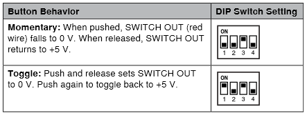
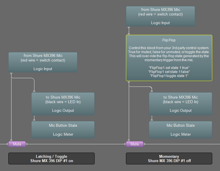
If DIP switch 1 is in the UP position, the mute switch will behave like a toggle switch. If DIP switch 1 is in the DOWN position, the mute switch will behave like a momentary switch.
LED control
The LED ring will light up green when there is less than 1V across the black and silver conductors (i.e., logic output in the low state), and it will light up red when there is 5V across the black and silver conductors (i.e., logic output in the high state).
Note that Shure MX series microphones use phantom power to power its LED's. Therefore, no external power supply is required for this application.
Further reading
- Once the device is physically connected to the EX-LOGIC, you'll need to program it. See EX-LOGIC programming for more information.
- Muting microphones with logic
- Shure MX396 Logic example file