RED-1 programming basics: Source Selection
This article explains how to setup a RED-1 to perform level control and source selection using the Source Selection DSP block. Alternately, the video below describes the same concepts.
Goal
After completing this article, you will have programmed the RED-1 to control a 4-channel Source Selection DSP block. The RED-1 will be able to select a particular source and immediately allow for adjustment of the level of that source after it has been selected.
DSP components needed
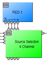 DSP components we'll need within the file include the RED-1 (4 logic outs) and the Source Selection (4 inputs, with Logic enabled). You will need to connect the logic outs 1-4 of the RED-1 to the logic inputs of the Source Selection. You will need to compile at this point to allow the software to generate Instance ID and Object Code designations for the component objects.
RED-1
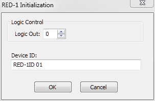
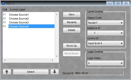
Double-click on the RED-1 to open the control dialog. Click New to add a new Control Item. It will appear in the column on the left as "Control Item 1". You can customize the name by highlighting the name and clicking the Rename button or hitting the Enter key. If you want it to be blank you can just enter a space in the text field.

On the right side of the RED-1 dialog you can assign a Level Control function and/or a Logic Control function for the Control Item. These are not required to be assigned, for instance, if you want an purely informative label vs a functional label.
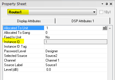
Level ControlThe Level Control is assigned using a combination of either the Object Code or the Instance ID, both refer to the same control object, and the Control ID which points to the specific control (eg - fader) within the object. Each Component Object or Block is assigned a unique Object Code and Instance ID. Object Codes consist of a device name followed by a number to distinguish it from similar objects (eg - Router1, Router2, Router3, etc.) They are unique to each object. The Instance ID can be discovered by looking at the Property Sheet | DSP Attributes for the Component Block you are interested in. The Instance ID is assigned to an object by the software when the file is compiled, it is fixed and will not change. Instance ID numbers are assigned to objects in the order which the objects were added to the design. An Instance ID is unique to each object.
|
Logic ControlThe Logic Control assigns a logic output node that is triggered by selecting this control item. The RED-1 can have up to 32 logic nodes added to it. Logic can be used for many things, some of which are: to trigger presets via the Remote Preset block, or use a flip-flop gate to hold an indicator on the RED-1. The Logic Out count can be modified by right-clicking the RED-1 block and choosing "Edit Block Parameters".
|
For the purposes of our example we'll want to create a total of (4) new Control Items and give them names, and assign them each Level Controls to link to. The level controls will reference the Source Selection component object.
The Level Control > Object Code should point to "Router1". When this is assigned, the Instance ID will fill in automatically, and the Control ID should refer to the "Input level n" for the input being defined (1,2,3, or 4).
You will need to assign the Logic Control > Logic Index so the number matches the Control ID "Input Level" channel number. This logic output will trigger the Source Selection to activate Source1-4, depending on which nodes are linked.
Result
Since we are also calling the Input Level control for the same input that we send a logic pulse to we get the resulting behavior:
- Select "Choose Source n" where n = 1...4
- the RED-1 sends a logic high pulse to the Source Selection block, activating that source
- the RED-1 sends a volume adjustment command and opens a screen for adjusting the volume of that source, when adjustments are finished, tapping the RED-1 will return you to the primary screen
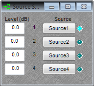
Once you are online you can test the controls from either the RED-1 or the PC. On the PC, use the up and down arrows and Select control below the Control Label window to toggle controls or double-click on the name to activate it. Logic functions do not work while the system is offline.
Further reading
For added functionality, continue on to read the article on How to control the triangle indicator on the RED-1.