Two-zone Qt X masking and paging hybrid with distributed audio example
Overview
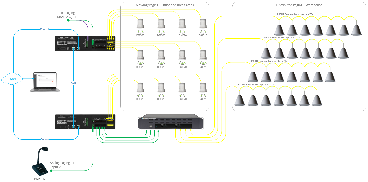
In this design template example, Qt X platform hardware provides centralized control of masking and paging in a facility with an office and a warehouse area. The space is already equipped with distributed warehouse paging speakers.
- In addition to paging, masking is required in the main office areas.
- The design will have two paging origination locations to serve each area.
- The front office area will have a telephone paging interface to allow for an extension of paging into the office and warehouse areas.
- In the warehouse area, a paging station will be available to page into the warehouse areas only.
This example design shows the required devices for this application.
System design
Sound masking, music, and paging system functionality scope:
- 2 Sound Masking Zones to accommodate
- Open office space
- Break Areas
- Warehouse distributed speakers using existing 70v amplification
- 1 telephone page interface to allow for extension dialing into the overhead paging systems.
- 1 Paging Station to provide live paging from the reception area.
- Zones served by each paging selection will be defined in the Qt X configuration file.
- Devices will be run in dual cable mode to allow for access to the owner network with AVB routed directly between devices.
Equipment list
Biamp equipment used in this project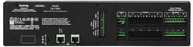
-
(2) Qt X 805 Masking Generators
-
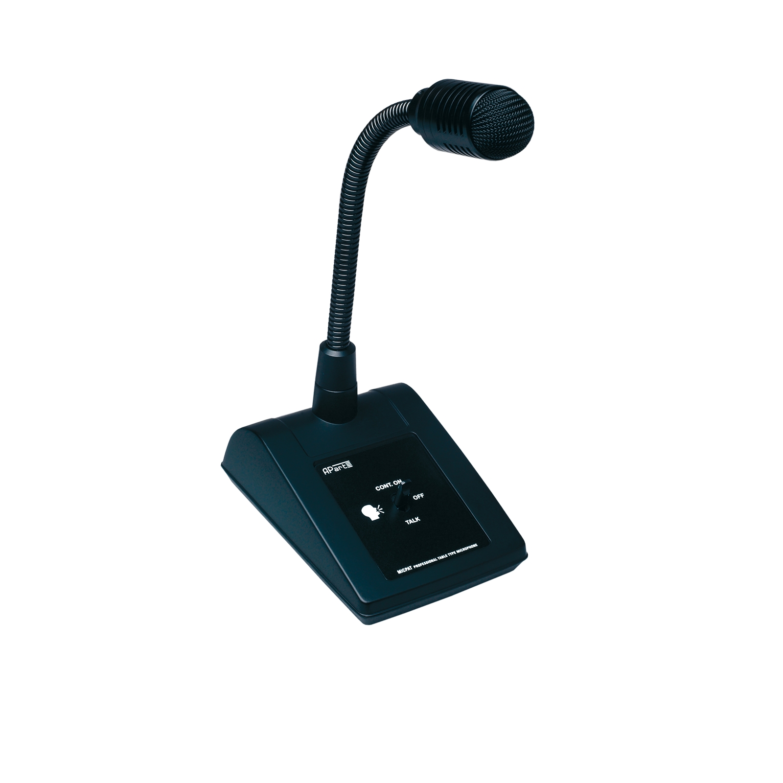
(1) MICPAT-D Tabletop all call paging microphone
-
12 DS1320 Qt® Active Emitters
Owner furnished equipment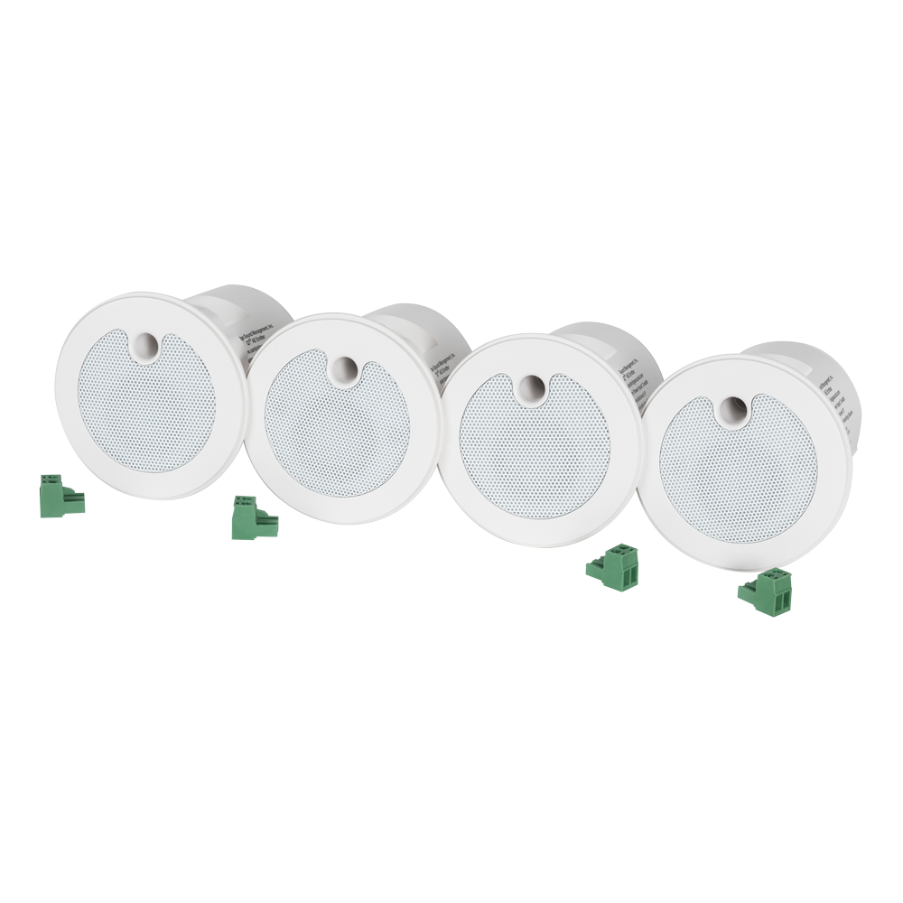
- An existing-4 channel amplifier and distributed warehouse speakers are owner provided and will receive audio inputs from Qt X 805 masking controllers to serve the warehouse paging zones.
- Telephone paging interface with line level output and contact closure trigger to active page in zone.
Example Files
The example file for this system design template includes the Qt X configuration file programmed to fit the design criteria for this design. It may be changed as needed or used as a reference for other designs. The Qt X software application may be downloaded here to open the configuration file for this design.
File Download
The file below contains the example Qt X .qdd configuration file for this application.
Networking details
The Qt X controllers specified in this design use AVB media to transmit source audio between devices. AVB will be directly connected between controllers eliminating the need for an additional AVB switch. Each controller will be connected via Port 2 to the owner network for device discovery and configuration.
The host PC will need to be on the same subnet or set to link local to discover the Qt X controllers via the address assigned to Port 2. Verify the PC's network settings are in the same range as the IP for Control/Media on the front panel of the controllers.
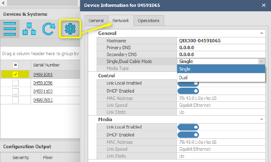
By default, all Qt X controllers are in Single Cable network mode with DCHP enabled. For this design, the controllers will need to be changed to dual cable mode from the Qt X software or Web UI.
Qt X Software: Device Information/Network
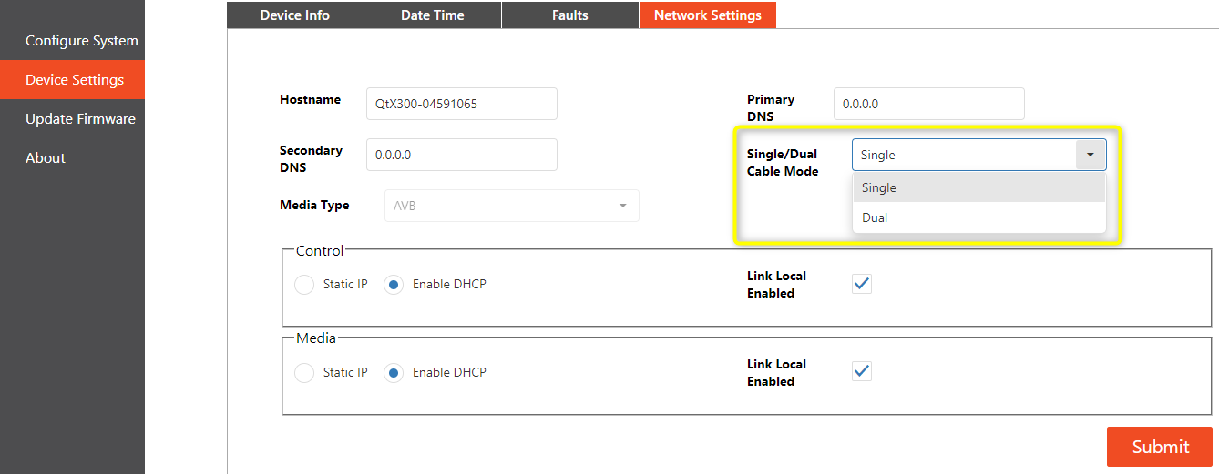
Web UI: Device Settings/ Network Settings
IP addressing may be left set to DHCP on the control interface port or assigned a static IP address based on the site requirements. The AVB ports on each controller may be left at DHCP to use link local addressing as they will not touch the larger network.
System set Up
This design file is configured for the Qt X controllers in the template's equipment list. The configuration file does not require physical hardware to view design and make edits. This file can used be a point of reference for understanding controller and zone programming as it applies to this design.
To load this configuration to hardware, the available hardware needs to be same model number as shown in the design with factory configuration cleared to allow assignment of blocks to physical devices. Devices all need to be set to the same media type.
Set Up Overview
Devices: The Qt X controllers may be replaced as needed to match available hardware to test functionality. The design software elements allow for adding or removing controllers from the toolbar to floor plan design. The (2) Qt X 805 controllers required for this design have been added.

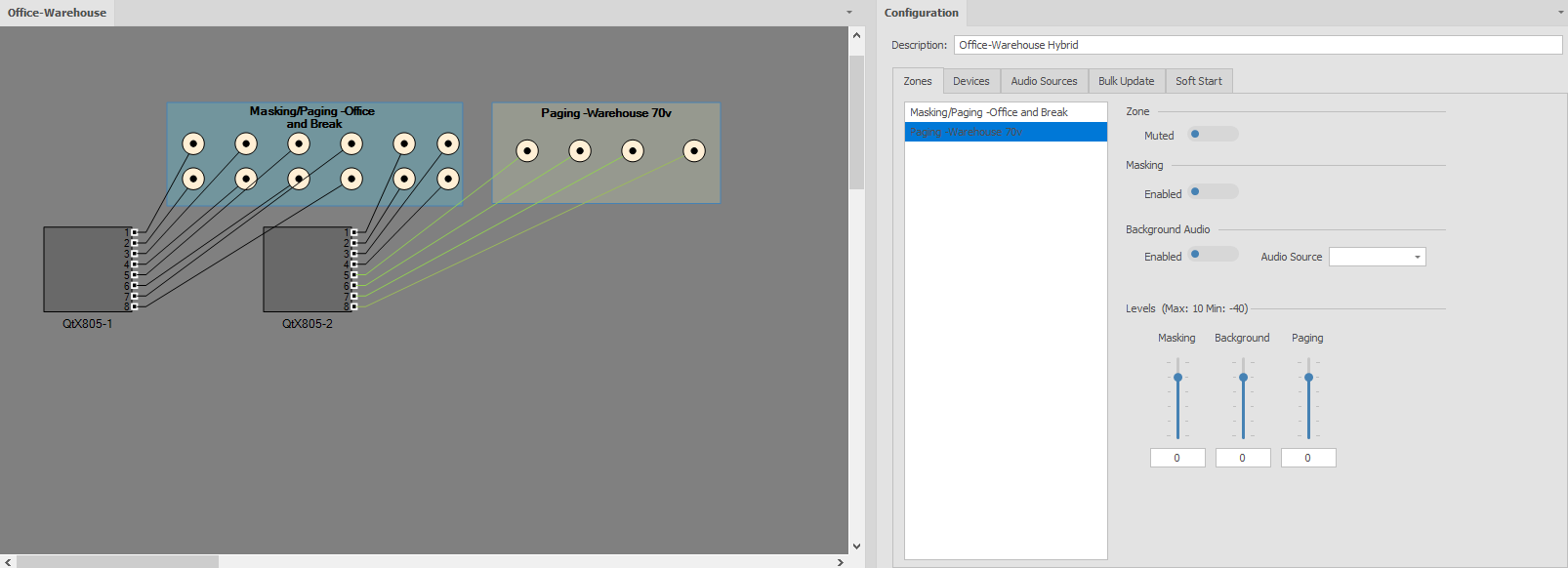
Zones: The design will have all the required zones and emitters added to properly meet the scope requirements. Zones have been named in the properties window to match the design drawing. Default zone colors have been changed to help with visualization on the floor plan.
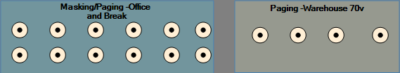
Note: It is important to note that the emitter icons are representative of a run of emitters or a single emitter speaker. It is not required to draw all speakers in the floor plan view.
Device configurations
QtX805-1 & QtX805-2
Emitter types
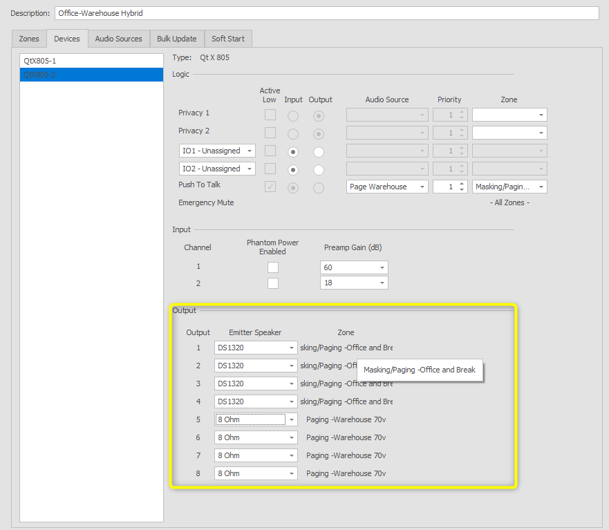
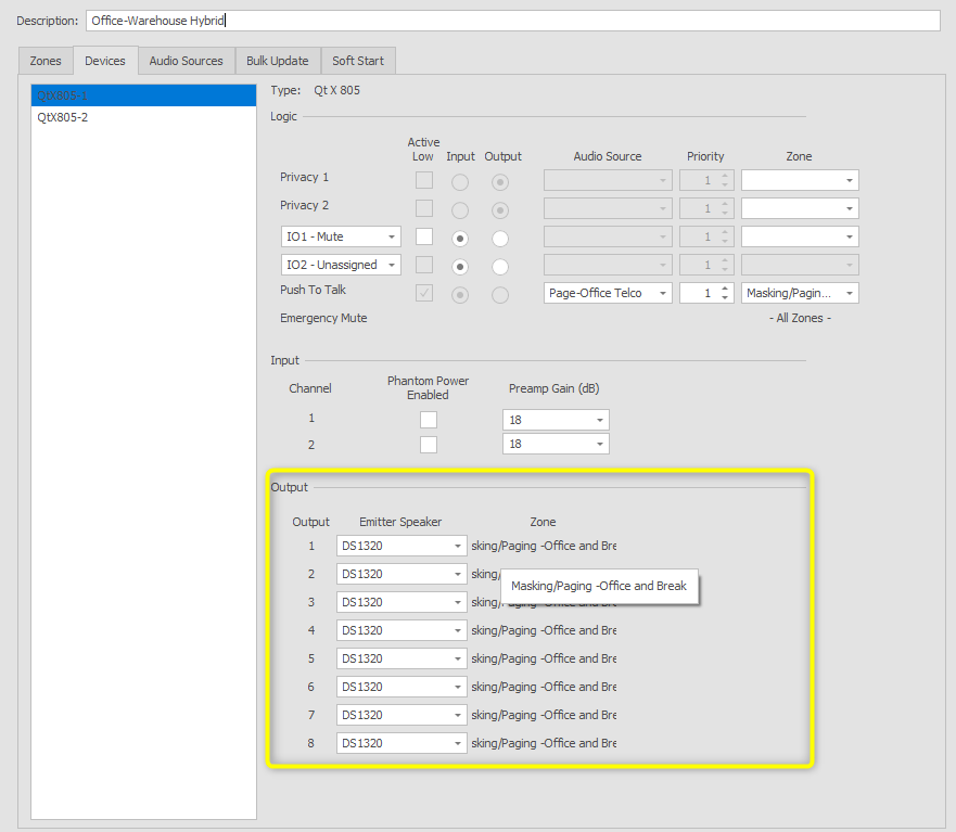
All emitters in the configuration file are set to match the zones’ sources. The open office and Break areas are assigned as DS1320. This setting is located under the Devices tab in the Output panel. The line level outputs that feed to the distributed system are setup up by default and do not require additional configuration. It is important to note that the line level outputs mirror the powered outputs on the controller. Due to the inability to separately adjust settings between line level and amplified outputs of the same number, we recommend that only one output type be used for each number in most applications.
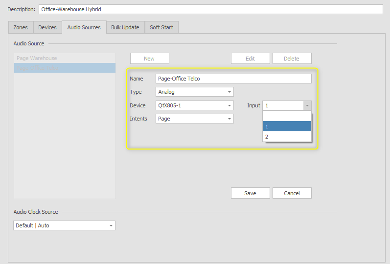
Audio Sources
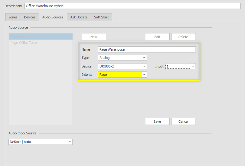
Analog audio sources have been added and assigned to devices to support the telephone and desk paging requirements. This application will be configured using logic inputs to trigger paging to zones.
Note: Input sources may be set up to serve as background, paging, or both. In this application, both sources have been selected as page in the Intents dropdown. This allows the inputs to only be available to assign to a logic input. It is recommended to use logic to trigger paging sources to the required zones rather than assigning them to a zone at all times. This allows for paging to only be active while required and at the same time duck any background music source. Paging input sources will be programmed in the logic section of this application.
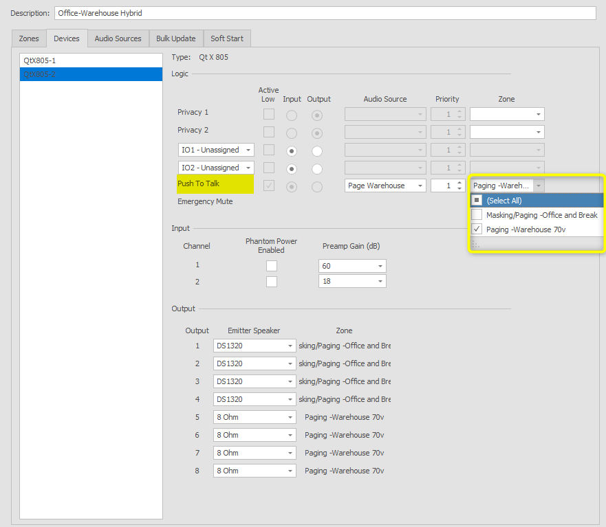
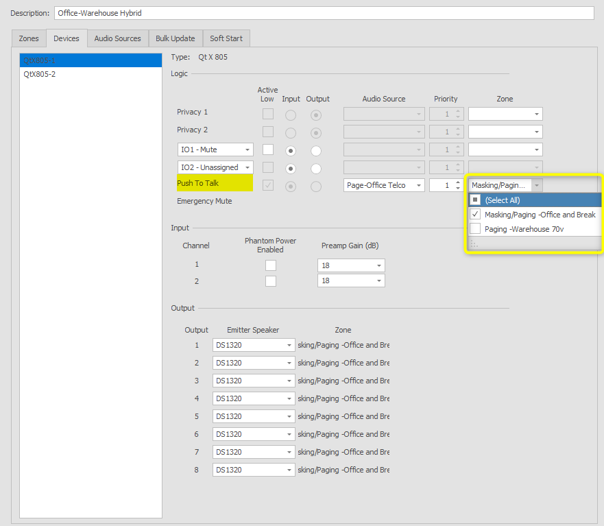
Logic
Contact closure inputs 2 on each controller are programmed to trigger Push to Talk pages to the selected zones. Both inputs default to active low to allow paging to be active when a contact closure is sensed. Paging sources are connected to the controllers based on closest proximity to reduce cable runs. The dropdown menus allow for selection of required zones.
Source input gain and phantom
Source input gain and phantom power assignment may be set during configuration or after a file is sent to the hardware. All analog inputs default to 18dB and can be increased or decreased in 6dB increments. Live metering is available on running configurations to allow for proper gain staging of inputs to ensure the best signal-to-noise ratio. In this scenario, the telephone paging input will be left at 18dB, while the paging microphone input will be raised to +48dB.
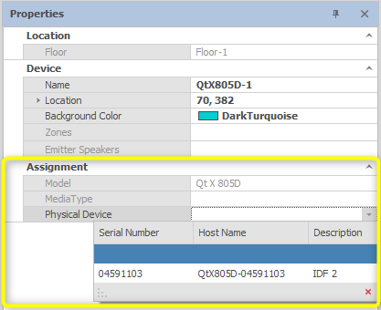
Device assignment
All Qt X controllers ship with a running default configuration file. When a design is created in Qt X software, devices can be added but not yet associated with the actual hardware that will be installed. This allows for configurations to be done with no hardware present.
Clearing configurations: Before a new configuration can be loaded to the hardware, the default configuration must be cleared. On the old configuration has been removed, devices may be assigned to blocks in the software from the properties window.
- To clear a configuration, select the system from the devices and system tab, then clear the configuration.
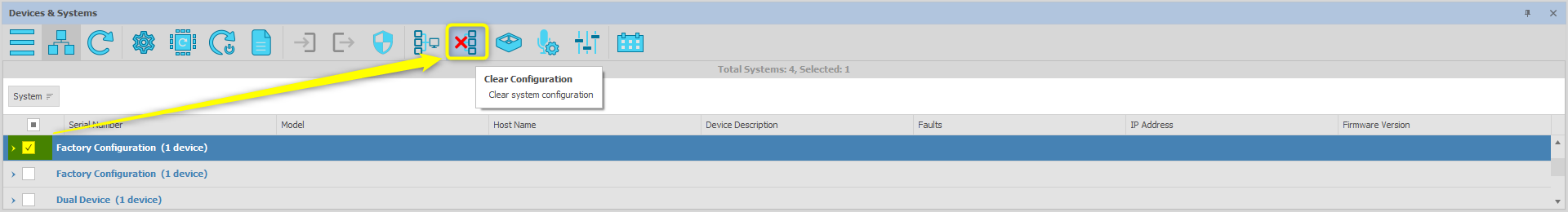
Once the device(s) have been cleared, they will be available to assign to the devices in the configuration file via the properties window.