Multicast traffic and IGMP
This article describes concepts and theory related to using IGMP, IGMP snooping, and AVB to operate networks requiring multicast AV traffic.
Background
Basic network switches provide network devices the capability to communicate within a single broadcast domain. A single broadcast domain network requires little to no configuration, but lacks the scalability required to meet bandwidth demands of complex AV networks.
The solution to complex AV networks rely upon switching and routing network topologies. Switching and routing together provide scalability, bandwidth, and administrative controls over logically separated network traffic creating the means for a very robust network solution. Managed switches use VLANs to segment layer 2 broadcast domains while leveraging routers to forward packets between VLANs to physically and logically distant networks.
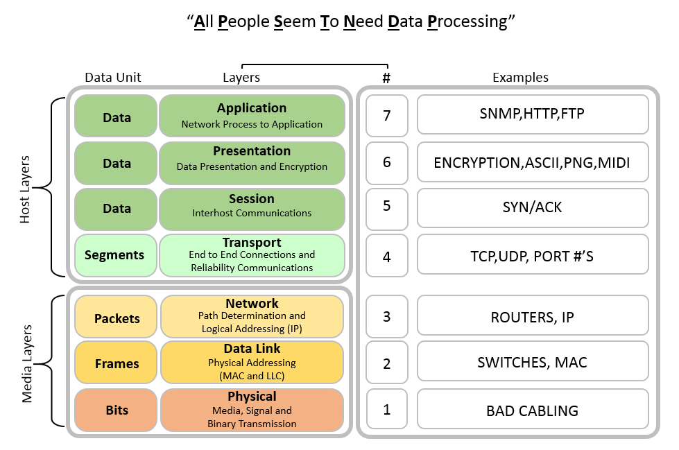
Networked AV devices, switches, and routers communicate using unicast, multicast, and broadcast protocols that follow the Open System Interconnection (OSI) model
The OSI helps visualize the hand-offs related to the specific jobs and protocols performed at each layer during data transfers occurring on the network.
The Institute of Electrical and Electronics Engineers (IEEE) developed IP multicasting protocols with the Internet Group Management Protocol (IGMP) to deliver single streams of information to multiple recipients, guaranteeing that all group members can receive messages, all group members can send messages, and group members can leave and join groups dynamically. These IGMP protocols operate at Layer 3 (Routing).
At Layer 2 (Switching), the Internet Engineering Task Force (IETF) developed "IGMP Snooping" to allow switches to work with the Layer 3 (Routing) IGMP protocol.
To solve the problem of needing to traverse Layer 2 broadcasted traffic through routed networks, devices rely upon the concept of using Layer 3 broadcast overlays based on IP multicasting protocols, IGMP, and IGMP snooping.
Types of traffic
Where traditional IP communication over hubs and switches allowed a device to send packets directly to another single device (unicast transmission) or to all devices (broadcast transmission) on the network, the need for IP multicast created a third possibility for allowing hosts the ability to send packets to a subset of all hosts as a group transmission.
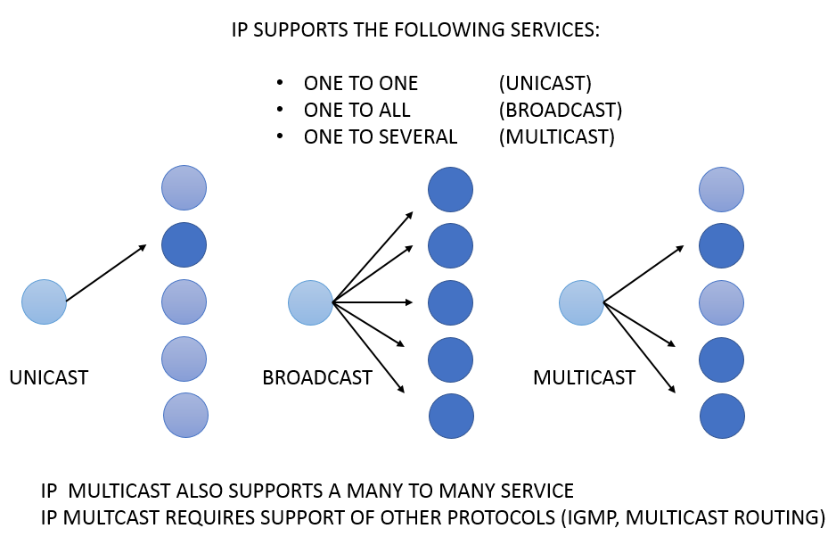
Unicast
Unicast traffic describes packets sent to a single destination interface using any pathway available traveling point to point on the network. This traffic type requires one sender and one receiver sending packets with session-based protocols like Transmission Control Protocol (TCP) and User Datagram Protocol (UDP).
Common transfer mode examples of TCP are http, telnet, smtp.
Common transfer mode examples of UDP are VoIP, video conferencing, streaming media, real-time services.
Broadcast
Broadcast traffic describes a single device sending communications to every other device on the network. Common examples of broadcast traffic on LANs include ARP messages querying all computers on the LAN. Remember too that broadcast traffic is not routable traffic.
Multicast
Multicast enables a single copy of data transmission from one node to multiple recipients. The transmitting device will forward UDP packets to a multicast IP address and port so all destinations that want to receive the stream can receive the transmission saving bandwidth and network overhead.
Multicast traffic is routable traffic but requires IGMP and PIM to control flooding the entire network, saturating uplinks, and potentially taking the network down.
Multicast overview
Multicast routing protocols require edge devices (i.e. PCs and AV devices) to tell routers about their desire to receive multicast streams from sending devices.
The sending devices define the "roots" of the "distribution tree", sending their traffic to the "branches" of the tree (routers and switches) who then forward it to the "leaves" of the tree (the requesting endpoint devices). Distribution trees are created via the routers using group membership protocols to learn about senders and receivers that want to talk to each other.
Multicast network requirements
Multicasting networks can be as simple as a single switch, or as complex as spanning an entire enterprise network. In all cases, the level of services required will vary needing to be configured according to the application.
At a minimum, layer 2 multicasting requires:
- · Managed switches from the same vendor
- · IGMP Snooping
- · IGMP Querier (Designated Querier, allowed one per subnet, typically a router unless no routers exist you can set a core switch in the network to carry out this duty)
- · A form of Spanning Tree Protocol (STP, RSTP, MSTP)
Networks requiring Layer 3 Multicast Routing support will require enabling their routers to support a multicast routing protocol using one of the Protocol-Independent Multicast (PIM) options and should additionally apply QoS along with storm control for broadcast and multicast.
Multicast scalability
Multicast traffic is transmitted using one of three common variations:
One to Many 1:M Concerts, TV, stock tickers, announcements, Network time
Many to Many M:M AV Conferences, whiteboards, collaboration, video gaming,
Many to 1 M:1 Video surveillance, polling
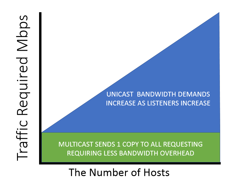
In all transmission modes, the scalability advantages of Multicast over Unicast become apparent when comparing the number of hosts relative to the amount of traffic required:
Unicast VS. Multicast Scaling
Network traffic address types
A proper IP address and/or MAC address is required for a packet to reach its intended destination. When transmitting multicast packets, special address ranges are reserved specifically for multicast groups.
The table below shows that Class D IP addresses are reserved for the sole purpose of multicast groups:
Unicast vs. Multicast Addresses

Multicast address groupings
Multicast addresses do not explicitly define a collection of individual devices, instead they define a multicast group that endpoint devices can listen to and receive traffic from, or transmit traffic to. This results in a redirection of traffic via a router or server to all members of the multicast group. Multicast groups refer to specific sets of network devices that have requested to receive specific multicast transmissions.
Multicast IP addresses differ from other IP addresses because they do not get associated with a single device, instead they provide a destination-only address which identifies a group of devices. The group of devices that is associated with a multicast IP address is dynamic and changes over time as different devices join and leave the group.
The address groupings of the Class D IP Multicast range from 224.0.0.0 to 239.255.255.255 is further divided into three multicast address groups:
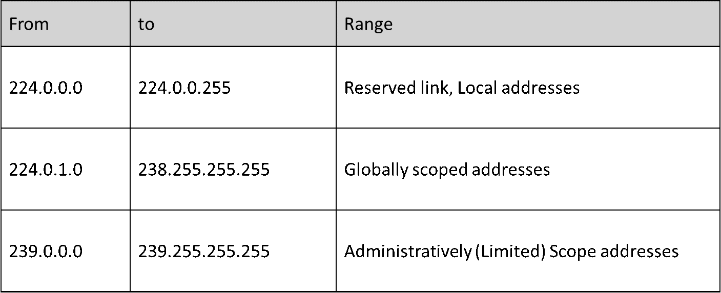
Locally scoped (reserved link local) addresses
- · Reserved by the Internet Assigned Numbers Authority (IANA) for network protocol use.
- · Fall in the Address range from 224.0.0.0 through 224.0.0.255
- Multicasts in this range are never forwarded off the local network, regardless of Time to Live (TTL). Typically, the TTL gets set to 1.
Some common examples of other network protocols in this address space include OSPF, EIGRP, RIPv2, VRRP, PIM, which are multicast protocols specific to routers.
Note that most multicast applications operating in this link-local address scope, including routing protocols, do not subscribe into their multicast groups via IGMP because it is technically not necessary for link-local multicasts to get forwarded beyond a router.
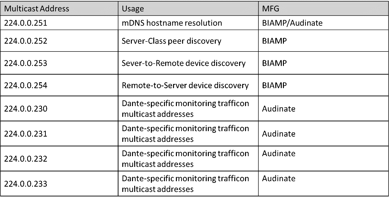
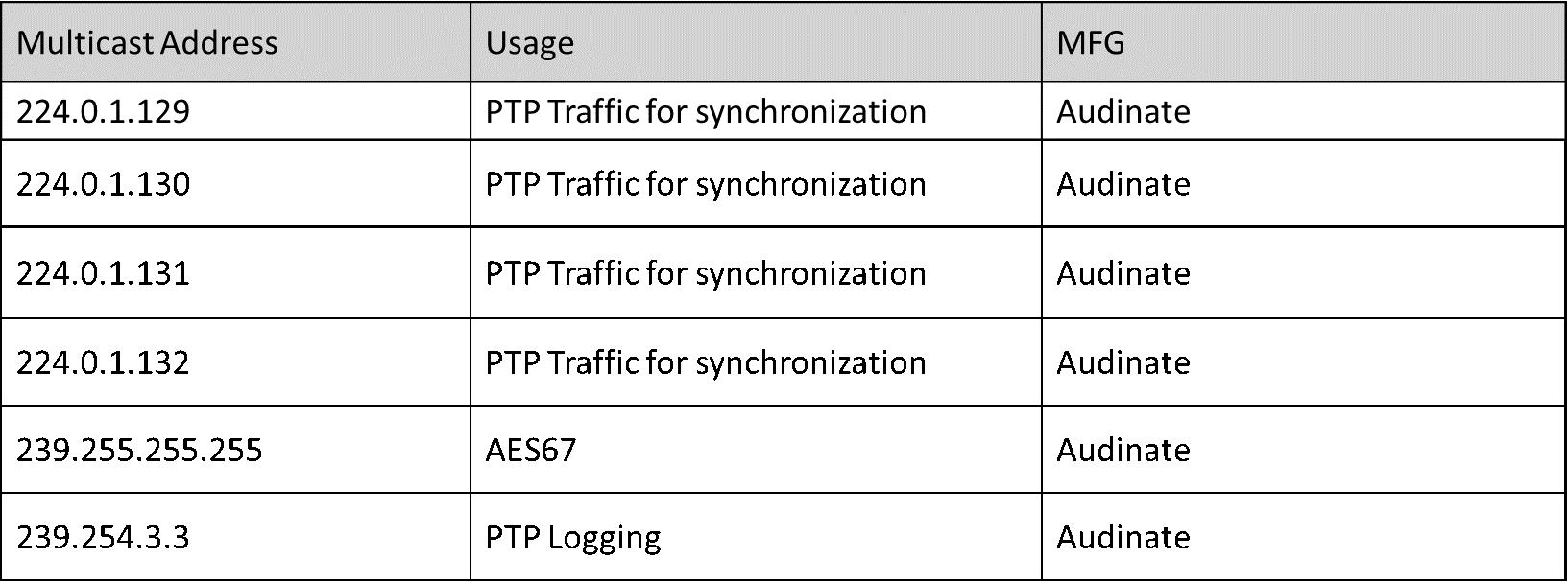
Biamp and Audinate locally scoped addresses for device communications
Globally and Administratively scoped addresses
Globally scoped addresses fall in the range of 224.0.1.0 through 238.255.255.255.
The familiar protocol falling in this range is 224.0.1.129 utilized for the Precision Time Protocol (PTP) which is used to synchronize clocks on a network. PTP packets will be sent for clocking in Dante communications.
Administratively scoped addresses 239.0.0.0 through 239.255.255.255 are reserved for use inside private domains. This address range is similar to the private IP address space used within the boundaries of a single organization. Administratively scoped addresses are constrained to a local group or organization.
Best practice setups should avoid using the reserved link local and globally scoped address ranges sticking with using the range 234.0.0.0 to 238.255.255.255 while also avoiding streaming with addressing in the (224-239).0.x.x and (224-239).128.x.x ranges due to multicast mac addressing overlap issues which can also occur within the link local block of addresses.
Multicast destination MAC Addresses
While IP addresses are reserved for multicasting at layer 3, getting multicast to work on layer 2 traffic requires MAC addresses and Ethernet frames. This raises the question, "How does a router or a switch relate a multicast IP address with a multicast MAC address?"
Standard Network Interface Cards (NICs) on a LAN segment only receive packets destined for their burned-in MAC address relying on Address Resolution Protocol (ARP) to find out the hardware (MAC) address of a device from an IP address. However, there is no equivalent to the Address Resolution Protocol (ARP) for multicast address mapping.
As a result, multicast MAC addresses are derived from the multicast IP address that is being used. This means that multicast MAC addresses are not hard-coded to a piece of hardware like typical MAC addresses are.
All MAC addresses always begin with the organizationally unique identifier (OUI). For multicast MAC address, the OUI is always 01:00:5e. After the OUI, the multicast MAC address is padded with a binary 0. The remaining bits of the multicast MAC address are derived from the multicast IP address.
When converted to binary, a multicast IP address will always start with a fixed 4-bit header of binary 1110 (due to the restricted IP address range for multicast). This leaves 28 bits of significant ipv4 addresses remaining that are used to relate a multicast IP address with a MAC address. However, after the OUI and the binary 0, the MAC address only has 23 bits left. So, some of the bits of the IP address are shaved off to fit within the remaining space of the MAC address. The diagram below illustrates the derivation of a multicast MAC address.
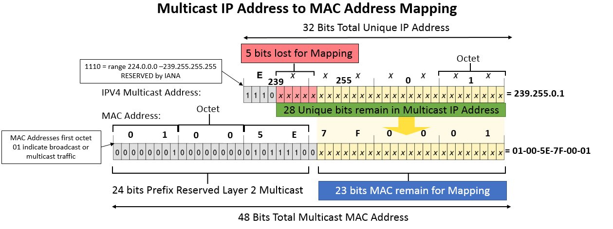
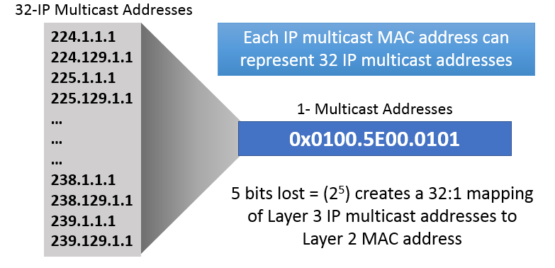
Since 5 bits of the IP address are lost in this transformation, there is never a 1:1 relationship between an multicast MAC address and a multicast IP address. In fact, every multicast MAC address has 32 multicast IP addresses that map to it. This can potentially create confusion and cause multicast packets to be delivered to devices that don't want them. These unwanted packets can be filtered out at layer 3, but this filtering can consume CPU resources, especially if the bandwidth of multicast traffic is high.
Preventing this requires using known local or existing multicast broadcast addresses when working in IP multicast environments avoiding multicast over the 239.0.0.0/24 and 239.128.0.0/24 subranges.
Multicast routing protocols
“Multicast routing protocols enable a collection of multicast routing devices to build (join) distribution trees when a host on a directly attached subnet, typically a LAN, wants to receive traffic from a certain multicast group, prune branches, locate sources and groups, and prevent routing loops.”
Protocol Independent Multicast
Multicast routing protocols evolved over time to the most common one applied today: Protocol Independent Multicast, or PIM. The protocol gains its independence through leveraging other unicast routing protocols on the network i.e. RIP, EIGRP, OSPF, BGP, or static routes via Reverse Path Forwarding (RPF) to define its traffic patterns.
Reverse Path Forwarding (RPF) ensures traffic will always flow away from the root of the tree keeping source to destination traffic patterns intact. Routers will look at the source IP address on received packets to determine if the packet arrives on the same interface the router would use to send traffic back to the source requesting it. The packets that match make the branches of the tree leading back to the source.
The PIM router runs an RPF test seeking a match in its unicast routing table to confirm if it should drop or forward the packet. To forward the multicast traffic, passing the RPF test, the next-hop interface used to reach the source address will need to match the interface the packet was received on.
PIM Dense Mode applications fall under smaller local area network LAN topologies not worried about bandwidth constraints, i.e. IPTV or Webcasting expecting vast numbers of receivers, referred to as a “Push model.”
PIM Sparse Mode applications fall under large WAN topologies looking to conserve bandwidth, i.e. teleconferencing applications expecting limited number of receivers of the stream, referred to as a, “Pull model” and will rely on a Router defined Rendezvous Point RP to centralize the exchange of the known active sources and forwarding of the multicast packets to other routers participating in the PIM-SM topology and has the best scalability preventing edge-to-switch link saturation and network loops from occurring.
PIM Sparse-Dense Mode allows for both modes operating on a per-group “either or” application. The rules for each mode will apply based on their group assignment of Sparse or Dense providing best of both worlds. Note best practice is not to run dense mode on WANs.
PIM Dense and Sparse mode differ in that PIM Dense mode packets flood to the entire network pruning branches where there are no receivers requesting streams “flood and prune protocol” and PIM Sparse mode packet branch distributions grow with nodes seeking to join the multicast group behaving as a “join protocol”.
Through the PIM process, multicast distribution trees will form. Multicast trees require a root, branches and leaves. The hardware equivalent would be the source of the multicast stream (Root). The source will send its traffic into the network to a multicast address. The source does not have any knowledge of the hosts that want to listen or receive the stream it sends. The traffic will be sent to routers and switches (Branches). Every router along the path becomes a fork in the tree, if the router learns about multicast groups existing branches are formed and where interested receivers exist (Leaves) traffic gets forwarded.
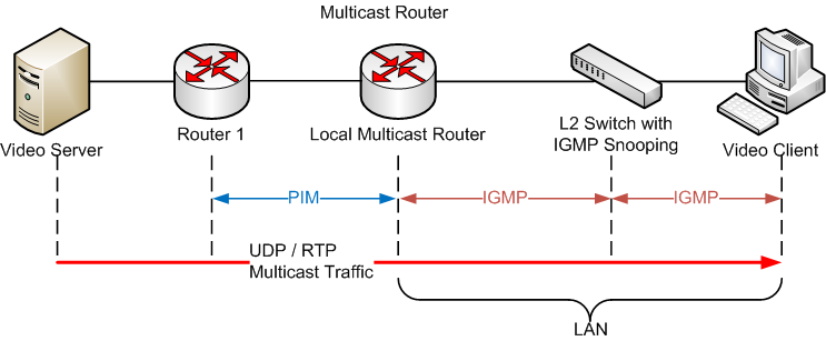
IGMP
Internet Group Management Protocol introduces the concept of IP multicast groups, raising the question of "How does a router or switch know which ports to send each multicast packet to?"
The answer is IGMP, Internet Group Management Protocol, which leverages a set of control messages that IP multicast-enabled devices send to each other to join and leave multicast groups.

Today’s AV streaming began using ethernet and network technologies but has evolved by leveraging existing technologies using IGMP or multicast routing. The issue is that IGMP was designed to enable streams to operate over the internet itself. For example, a video streaming service sends one copy of a video stream to the internet as a whole. This example allows any number of listeners or consumers watching the stream sent.
This could scale up to multiple streams being sent allowing the streaming service to operate similarly to the way CATV infrastructure behaves, offering multiple channels of live content allowing users to select channels to watch. In the CATV scenario, users select which channels they wanted to watch however in a network scenario channel selection adds latency when switching channels or streams.
To accomplish the equivalent of changing CATV channels on the network, users would leverage IGMP as the mechanism to select specific channels and control where those multicast streams go. Additionally, this is what allows the internet to support multicasting. IGMP provides the control over the multicast traffic administrating that it does not go anywhere until its explicitly asked. IGMP's importance here is that the internet would not be able to scale to the implementation we have today if we did not have this.
Remember that the I in IGMP is for internet, so what we are talking about here is a layer 3 technology focused on routed infrastructure, not switched infrastructure. IGMP behavior was designed for the internet where latencies are highly variable, and latencies are significantly longer than what you see in a local area network or switched infrastructure.
Routers also use IGMP to advertise multicast group memberships to neighboring switches and routers.
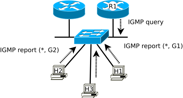
To function, Layer 3 aware devices listen to join and leave messages from clients wanting to join and leave multicast groups through use of an IGMP Querier, common setups rely on a Designated Querier (DQ) per VLAN. The IGMP Querier sends periodic IGMP Query messages to all multicast-capable hosts at the multicast IP address 224.0.0.1
The creation of multicast groups via the IGMP process begins with host devices sending their packets to a Class D multicast IP address destination identifying their intent for creation of a multicast group. The transmitting host also begins to send IGMP membership reports to 224.0.0.2 in the direction of all multicast routers specifying the multicast group address. Connected switches will add the multicast group into their multicast routing table, marking their receiving ports as members of a multicast group, and begin to forward that traffic to connected multicast routers. Connected routers will add those hosts to their multicast routing tables.
To maintain their participation as members of the group, hosts will begin sending join messages, adding them into the created groups and their traffic will only forward out of participating ports. Hosts that do not reply to the IGMP Querier in a specific period will be removed from the address group tables. Once all members have left a multicast group the switch will remove the multicast address from its table.
IGMP Snooping
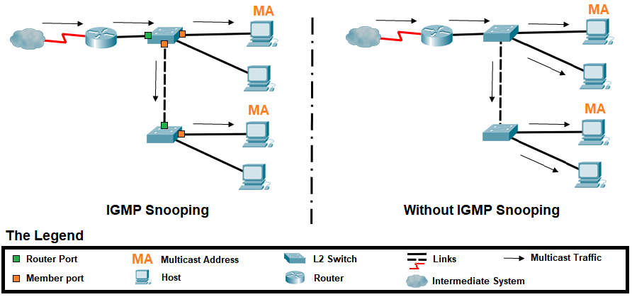
IGMP is a layer 3 protocol, which means that switches (operating at layer 2) should be unaware of it. However, if switches are unaware of IGMP, how can they know what ports to send a multicast packet to? The answer is: they don't. By default, a switch will treat a multicast packet like a broadcast packet, and send it to all ports, unless that switch supports IGMP snooping.
IGMP snooping is a switch feature designed to reduce multicast flooding, effectively preventing the switch from broadcasting everything that comes into the switch to all nodes on the switch. Instead IGMP snooping lets the switch listen to the IGMP joining messages to build a map of what ports actually want to be members of which multicast groups.
To fix the multicast flooding problem created by IGMP, IGMP snooping was implemented as a feature on switches allowing them ability to act the way an IGMP router operates, using IGMP messages to determine what switch ports will forward and receive multicast traffic. Through the snooping mechanism, the receivers' IGMP join and leave messages exist so the switch can process how many copies to make of the multicast transmissions and decide on which ports to forward those packets.
The IGMP version used by the switch must match the sending host in order to be functional, IGMP v3 is backwards compatible to 2, and 2 to 1. It is best to match the versions so similar versions but should defer to manufacturer for appropriate version.
IGMP is the protocol that devices use to send a message to tell the switch they want to receive a stream; the join request gets sent to the switch and the IGMP snooping table gets populated and mapped to their respective port identifiers.
Multicast AVB
So far the scope of this article primarily covered IP multicast using layer 3 solutions with a layer 2 overlay. There also exists a dedicated layer 2 multicast solution for AV devices relying on Audio Video Bridging (AVB/TSN).
AVB works using a suite of network standards published/designed by IEEE (Layer 2) which allow digital audio and video signals to be transmitted over a standard Ethernet network. AVB protocols were designed to deliver low latency, multi-channel, uncompressed audio/video transmissions, using AVB-compatible network switches. AVB provides a solution outside of using IGMP and IGMP snooping to deliver multicast streams on the network working within Layer 2 on your LAN.
AVB-TSN networks provide robust network scalability with the least amount of configuration required to the network. This form of multicast creates a true plug and play multicasting solution removing many of the pitfalls and configuration requirements of traditional layer 3 multicast solutions. Once ports on the switch requiring AVB are enabled, the automation of AVB protocols handles the remaining configuration within the AVB network. This reduces misconfigurations and saves time in configuring and troubleshooting your multicast network.
Conclusion
Multicast networks will vary. They might only occur in a single switch, hop multiple switches, or connect to routers across your customer’s enterprise network. The intent of this article seeks to provide the conceptual understanding to describe the main components required for AV network functionality using multicast.
Remember that when implementing IGMP snooping, the burden does not fall on the switch or switch manufacturer, IGMP snooping functionality relies on many non-automated modifications to the network. This approach places administrative burden on configuring of the endpoints ingress to support IGMP Snooping (for multicasting) along with applying proper QoS at a minimum.
IGMP and IGMP snooping deployments also rely on endpoints to take the full burden of clock synchronization over a network with indeterminate latency and higher jitter potential which might find drawbacks in terms of the maximum network bandwidth (imposed by IGMP Snooping), source switching time (IGMP Snooping again), clock accuracy, and the amount of configuration and IT skills required of the integrator.
Lastly, IEEE AVB based multicast removes IGMP and IGMP snooping complexities preventing many issues that arise in traditional multicast networks, ultimately providing a layer 2 IEEE designed solution that automates and protects the entire network from AV traffic issues creating a truly plug and play AV network solution.
References & Further Reading
- https://support.biamp.com/Tesira/Con...trol_and_Dante
- https://service.shure.com/s/article/...language=en_US
- AMX. (2020). Multicast for Enterprise Video Streaming. Retrieved from https://www.amx.com: https://www.amx.com/en/premium-conte...ideo-streaming
- Beal, V. (2020). The 7 Layers of the OSI Model. Retrieved from https://www.webopedia.com: https://www.webopedia.com/quick_ref/OSI_Layers.asp
- Cisco Systems. (2020). Internet Protocol IP Multicast Technology. Retrieved from https://www.cisco.com: https://www.cisco.com/en/US/tech/tk8...0800a4415.html
- Cisco Systems. (2020). IP Mutlicast. Retrieved from https://www.cisco.com: https://www.cisco.com/c/en/us/tech/i...ast/index.html
- Dell. (2018). What is IGMP and how does it work? - Technical Tip - 132521. Retrieved from https://www.dell.com/: https://www.dell.com/support/article...132521?lang=en
- Etutorials.org. (2020, March 26). The Central Multicast Problem. Retrieved from http://etutorials.org: http://etutorials.org/cert/ccnp+bsci...dation+Topics/
- Extreme Networks. (2019, October 11). How To Pass Multicast Traffic on an Extreme Switch. Retrieved from https://gtacknowledge.extremenetworks.com: https://gtacknowledge.extremenetwork...fs=Search&pn=1
- Fairhurst, G. (2009, October 03). EG3557. Retrieved from https://erg.abdn.ac.uk: https://erg.abdn.ac.uk/users/gorry/c...i-b-mcast.html
- Network Lessons (2020). Introduction to Multicast. Retrieved from https://networklessons.com: https://networklessons.com/multicast...n-to-multicast
- IETF. (2006, May). Considerations for Internet Group Management Protocol (IGMP). Retrieved from https://tools.ietf.org: https://tools.ietf.org/html/rfc4541
- Indresøvde, E. (2019, April 18). IGMP and the Quirky Querier. Retrieved from https://www.ravepubs.com: https://www.ravepubs.com/igmp-quirky-querier/
- Ionos. (2020, March 26). Multicast: Point-to-multipoint connection for efficient data transfer. Retrieved from https://www.ionos.com/: https://www.ionos.com/digitalguide/s...how/multicast/
- Johnson, V. J. (2020). How IP Multicast Works. Retrieved from https://www.csie.ntu.edu.tw: https://www.csie.ntu.edu.tw/~course/...ipmcworks.html
- Juniper. (2015, Januray 19). Multicast Overview. Retrieved from https://www.juniper.net: https://www.juniper.net/documentatio...-overview.html
- Schluting, C. (2020). Networking 101: Understanding Multicast Routing. Retrieved from http://www.enterprisenetworkingplanet.com: http://www.enterprisenetworkingplane...st-Routing.htm
- Various. (2020). Understanding TCP, UDP and videoconferencing protocols. Retrieved from https://www.reddit.com/: https://www.reddit.com/r/networking/...oconferencing/
- wikimedia.org. (2020). File:Difference unicast multicast broadcast.jpg. Retrieved from https://commons.wikimedia.org: https://commons.wikimedia.org/wiki/F..._broadcast.jpg
- wikimedia.org. (2020). File:IGMP Snooping Example - en.png. Retrieved from https://commons.wikimedia.org: https://commons.wikimedia.org/wiki/F...ample_-_en.png
- wikimedia.org. (2020). File:Multicast Protocols - en.png. Retrieved from wikimedia.org: https://commons.wikimedia.org/wiki/F...ocols_-_en.png
- wikimedia.org. (2020). File:Protocol Independent Multicast. Retrieved from https://en.wikipedia.org: https://en.wikipedia.org/wiki/Protoc...dent_Multicast
- wikimedia.org. (2020). File:Osi-model.png. Retrieved from https://commons.wikimedia.org: https://commons.wikimedia.org/wiki/File:Osi-model.png
- wikimedia.org. (2020). File:IGMP LAN.svg. (2020). Retrieved from https://commons.wikimedia.org/wiki/File:IGMP_LAN.svg: https://commons.wikimedia.org/wiki/File:IGMP_LAN.svg
- wikimedia.org. (2020). File:IPv4 Multicast to Mac Address Swedish.svg. (2020). Retrieved from wikimedia.org: https://commons.wikimedia.org/wiki/F...ss_Swedish.svg