Creating a VLAN on the Netgear GS724Tv4
This article explains how to configure a VLAN on a Netgear GS724Tv4 network switch.
Like most managed switches, the Netgear GS724Tv4 provides the ability to segregate network traffic using Virtual LANs, or VLANs. There are many reasons to use VLANs, but perhaps the simplest and most common is to segregate different types of device from one another, especially when one or more makes heavy use of multicast.
For example, CobraNet's use of Ethernet multicast means it is good practice to isolate CobraNet devices by placing them onto their own VLAN. Similarly, Dante devices can make use of IP multicast, and implementing a Dante VLAN with IGMP Snooping will help maximize bandwidth by ensuring each multicast flow is sent only to the devices configured to receive it.
AVB audio automatically uses a dedicated VLAN (VLAN 2). The steps in this article are not required for AVB.
Log into switch
The switch can be configured via its web interface. By default, the switch will request a DHCP IP address. If no DHCP server is present on the network, it will self-assign an IP address of 192.168.0.239. Netgear's Smart Control Center application can be used to discover the switch on a network, regardless of its IP address. The application can be downloaded from the Netgear website or installed from the CDROM included in the box.
Entering the switch's IP address into a web browser will open the management console. The first page is the password prompt.

The default password is “password” (entered without quotes). Enter it and press the LOGIN button. The first screen the switch will display is System Information.
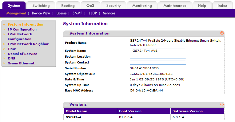
Figure 1 – Netgear GS724Tv4 System Information
Create the new VLAN
To view, add or remove VLANs, select the Switching tab, then in the menu bar select VLAN. The first section is VLAN Configuration, where we will create our new VLAN.
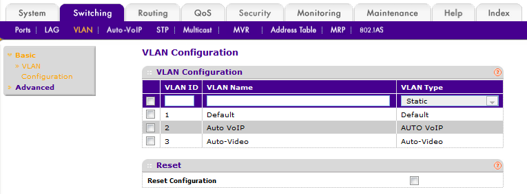
Figure 2 – VLAN Configuration Page
Pre-configured VLANS
The GS724Tv4 switch comes pre-configured with three VLANs, which cannot be deleted:
- VLAN 1 Default (the default management VLAN)
- VLAN 2 Auto VoIP (AVB audio)
- VLAN 3 Auto-Video
Add new VLAN ID and name
Enter a number for the VLAN ID (between 4 and 4093) then enter a VLAN Name, both must be unique on the switch. The VLAN Type should be left at the default setting of Static.
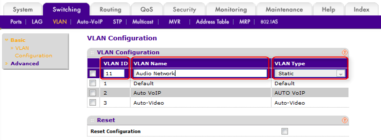
Figure 3 – Adding a new VLAN
Apply and check
Click the ADD button near the bottom right of the browser window, and the new VLAN will appear in the list.
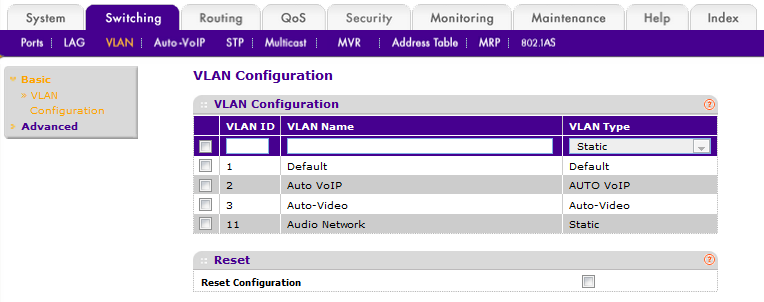
Figure 4 – new VLAN added
Assign network interfaces to new VLAN
In this example, we will add ports 5, 6, 7, 8, 17 and 18 to the new VLAN.
Note: Because neither CobraNet nor Dante supports VLAN tags, the ports must be assigned as untagged members of the new VLAN. A network interface can be an untagged member of one VLAN only, so after this next step the assigned ports will no longer be untagged members of VLAN 1.
Remove interfaces from AVB VLAN
On the Netgear GS724Tv4, the AVB VLAN, #2, is called the Auto-VoIP VLAN, and many of its features are configured in the Auto-VoIP menu.
Select the Switching tab then Auto-VoIP. This will display the page Protocol Based Port Settings, on which Auto VoIP mode (AVB) can be disabled for each interface.
Check the box for each port you wish to remove from the AVB VLAN. "g5" refers to Gigabit interface 5, so in this example we will check boxes g5, g6, g7, g8, g17 and g18. Once the ports are selected, change Auto VoIP Mode to Disable.
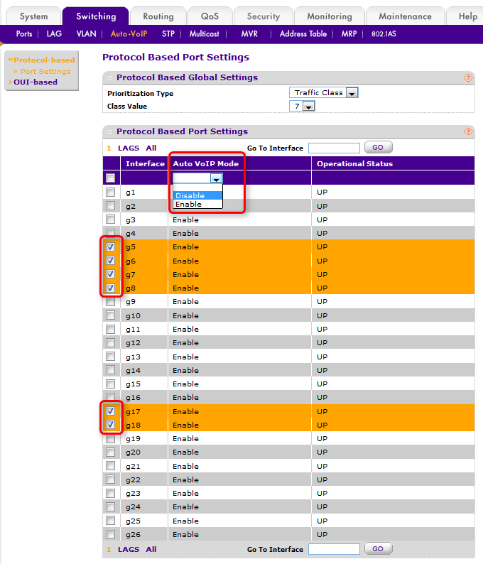
Figure 5 – Disable AVB
Click APPLY. The selected interface should now report "Disable" for Auto VoIP Mode and "DOWN" for Operational Status.
Set VLAN membership
Select the Switching tab, then in the menu bar select VLAN. In the menu on the left, select Advanced, then Port PVID Configuration.
Check the box for each port you wish to assign to the new VLAN, g5, g6, g7, g8 g17 and g18, in this example.
As shown in the figure below, enter the number of the new VLAN, "11" in our example, into fields Configured PVID and VLAN Member, and in the field VLAN Tag enter "None". All other fields should be left at empty or at their default values.
The new values will overwrite the existing ones, so the old VLAN assignment will be removed automatically.
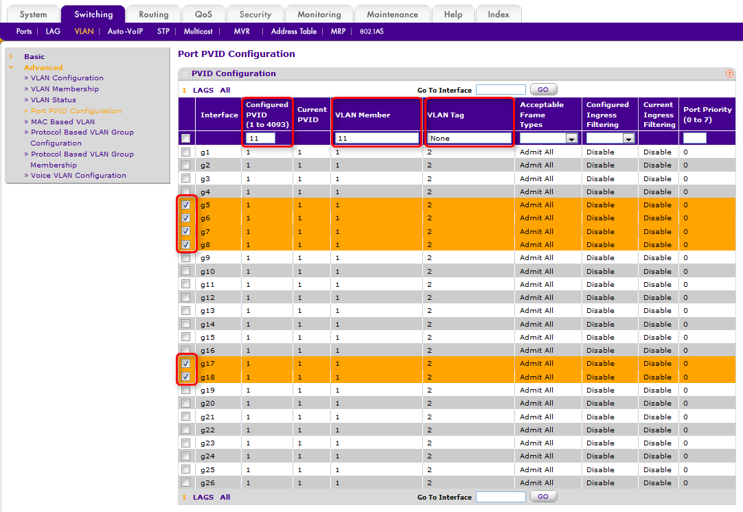
Figure 6 – New VLAN membership settings on page: Port PVID Configuration
Apply and check
Click APPLY and the VLAN 1 membership page should look like this:
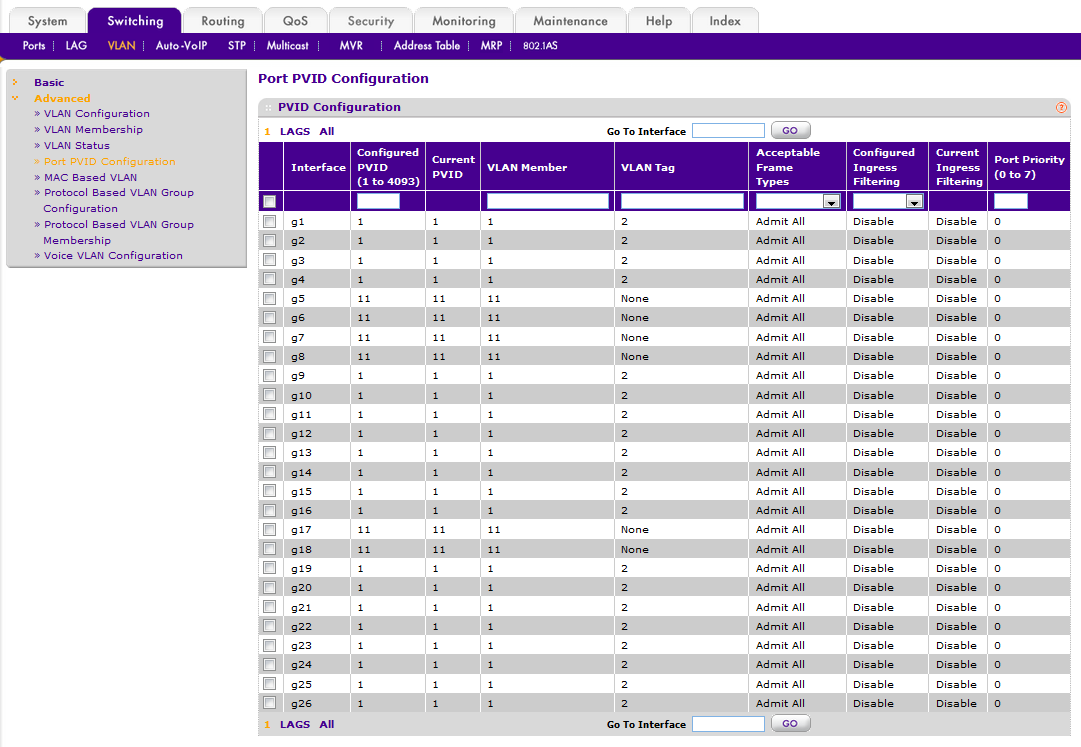
Figure 7 – New VLAN membership configured, on page: Port PVID Configuration
Summary
The above steps set the inbound (ingress) and outbound (egress) rules for ports 5, 6, 7, 8, 17 and 18, so that:
- Any incoming untagged Ethernet frames will be made part of VLAN 11 as they enter the switch
- These frames will be forwarded only to those interfaces which are also members of VLAN 11
- VLAN tags will be removed as the forwarded frames exit the switch, leaving them in their original untagged state.
For networks of one switch only, no further steps are required.
Note: you can also view and change VLAN assignments by in the VLAN Membership section. Select the Switching tab, then in the menu bar select VLAN. In the menu on the left, select Advanced, then VLAN Membership. Use the drop-down list to select which VLAN's membership status to view.
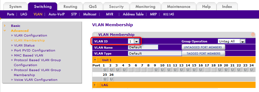
Figure 8 – VLAN Membership
Advanced - networks of two or more switches
When working with larger networks of two or more switches, it is possible to extend a VLAN across all switches in the network.
There are two steps to this process:
- Configure the new VLAN on every switch on the network, as shown in the steps above.
- Configure uplinks ports on each switch.
An uplink is a network port which connects to another switch, rather than a host device, and the key difference is how uplinks ports are configured. Because several VLANs may use the uplink, it must be configured such that traffic will remain segregated into the programmed VLANs. This is achieved by making the uplinks ports tagged members of the new VLAN. The reason for this difference is simple. The steps above configured the switch to add a VLAN tag to each incoming Ethernet frame, which will be used to internally to the switch but then removed as the frame exits the destination port. When a frame leaves an uplink, however, we want the VLAN tag left in place, so the upstream switch will correctly identify which VLAN the incoming frame belongs to.
In this example port 24 will be configured as the uplink.
Configure uplink
The default VLAN for the Netgear GS724Tv4 is VLAN 1. This is also the default management VLAN, i.e. the VLAN allowed to access the switch's management console.
By leaving the uplinks as untagged members of VLAN 1, we allow management traffic to share the uplink with our new VLAN. This can be very useful - it allows the administration of all switches on the network to be done from a single location.
Select the Switching tab then VLAN. In the menu on the left, select Advanced then VLAN Membership. This will show VLAN port membership for VLAN 1.
Port 24 will already be configured as an untagged member of VLAN 1. In this example, it will be left this way.
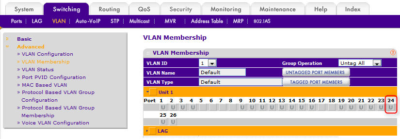
Figure 9 – uplink settings for default VLAN
Note: the uplink can be set as a tagged or untagged member of VLAN 1. Either would work, provided the same setting used for each switch.
In the VLAN ID drop-down list, select VLAN 11. This will show VLAN port membership for VLAN 11.
Click once on the box for port 24, which will set it to "T" for tagged.
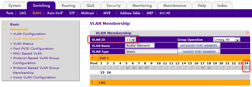
Figure 10 – uplink settings for new VLAN
Click APPLY to save this setting.
Uplink summary
Return to the Port PVID Configuration page by selecting Switching > VLAN > Advanced > Port PVID Configuration. The configuration should look something like the figure below.
As per the steps in the first section, ports 5, 6, 7, 8, 17 and 18 are configured such that:
- Any incoming untagged Ethernet frames will be made part of VLAN 11 as they enter the switch
- These frames will be forwarded only to those interfaces which are also members of VLAN 11
- VLAN tags will be removed as the forwarded frames exit the switch, leaving them in their original untagged state.
As per the steps in this advanced section, port 24 is configured such that:
- Incoming untagged Ethernet frames will sorted and tagged according to their VLAN ID
- frames without a VLAN tag will be made part of VLAN 1 as they enter the switch
- frames tagged as VLAN 11 will be forwarded as members of VLAN 11
- frames tagged as VLAN 2 (AVB) will be forwarded as members of VLAN 2
- Outgoing frames from VLAN 1 will have their VLAN tags removed as they exit the switch
- Outgoing frames from VLAN 11 and VLAN 2 will have their VLAN tags left intact
In this way, the traffic of these two VLANs can share the uplink, and be correctly identified by the upstream switch.
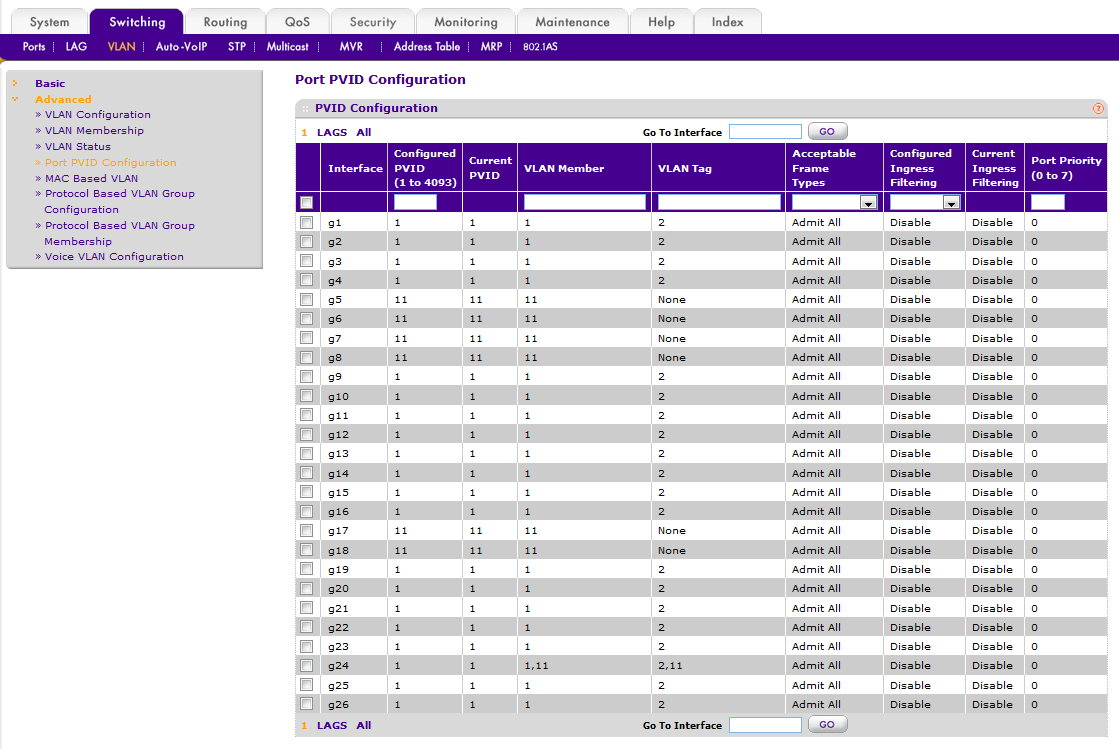
Figure 11 – summary of overall VLAN membership, on page: Port PVID Configuration
Uplink types
AVB
In this example the uplink is a tagged member of VLAN 2 for AVB. This is required if AVB audio is to traverse the uplink
CobraNet
If the new VLAN is intended for CobraNet audio, then CobraNet and AVB, on their respective VLANs, can share an uplink.
Dante
Dante and AVB cannot share the same uplink, even when configured to use separate VLANs. If the uplink is intended for Dante audio, 802.1AS support must be disabled on the port. Please see this document for more information. The uplink port should also be removed from VLAN 2, as per the section Remove interfaces from AVB VLAN #2: Auto-VoIP.