Configuring Audio-Technica Dante microphones
Tesira servers support native integration with Dante-enabled microphones manufactured by Audio-Technica. Specifically, the Audio-Technica ATND971 (boundary microphone), ATND8677 (microphone desk stand) and ATND8734 (ceiling plate module) are supported. The microphones are powered by PoE and transmit audio and control data over a Dante network.
A Tesira SERVER or SERVER-IO with a DAN-1 (Dante) card is required for use with these microphones. Similarly, TesiraFORTE DAN models can be used with these Dante-enabled microphones. Tesira software includes a specific input block (Dante Mic block) for this application, which includes several options for logic control of muting and LED functionality, as well as the ability to identify each microphone by flashing its LED.
A maximum of 32 AT mics can be connected to any DAN-1 card or TesiraFORTE DAN. The Audinate Brooklyn II card is limited to receiving a maximum of 32 Dante input flows, and each mic (device) presents a unique flow.
This article describes the software interface for configuring and controlling these Dante microphones, as well as some example configurations for common scenarios.
Dante Mic input block
 As of Tesira version 2.3, Tesira software includes a Dante Mic input block. This block not only passes the audio signals from the Audio-Technica ATND971 or ATND8677 microphones, but also manages the muting, logic, and LED functionality of the microphones.
Initialization dialog
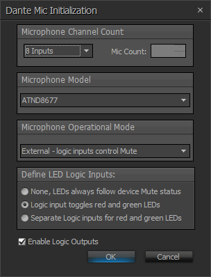
When inserting a new Dante Mic input block, the following options are available:
- Microphone Channel Count - choose how many channels this block will represent
- Microphone Model - choose the model of microphones being used
- Microphone Operational Mode - choose how the mute switch on the microphone will behave:
- Initially set to Mute, button press sets to Talk - each button push toggles the mute state, initially muted on power up
- Initially set to Talk, button press sets to Mute - each button push toggles the mute state, initially unmuted on power up
- Mute unless button is being pressed - mute button is momentary, also known as push-to-talk
- Talk unless button is being pressed - mute button is momentary, also known as push-to-mute
- External - logic inputs control Mute - mute button does not automatically mute/unmute microphone, muting must be manually triggered with logic signals
- Define LED Logic Inputs - choose how the microphone LEDs are controlled:
- None, LEDs always follow device Mute status - LEDs always represent the mute state of the microphone, red for muted, green for unmuted, no logic inputs available for controlling LEDs
- Logic input toggles red and green LEDs - a single logic input allows control of the LED, logic high makes it green, logic low makes it red. Logic inputs for LED control are labeled RG1, RG2, etc.
- Separate Logic inputs for red and green LEDs - two logic inputs per microphone, allowing independent control of red and green LEDs. Logic high turns the LED on, logic low turns it off. This is the only mode where it is possible to turn both LEDs off, or to turn both LEDs on (which results in a yellowish LED).
- Enable Logic Outputs - choose whether logic outputs are provided on the bottom of the block. If enabled, one logic output per channel will be available. If the Microphone Operational Mode is set to "External", the logic output will correspond to the physical push button on the mic base (logic high when the button is pressed, logic low when it is released). In all other Microphone Operational Modes, the logic output will follow the mute state of the microphone (logic high when muted, logic low when unmuted).
Control dialog
The control dialog of the Dante Mic block allows for typical microphone input functions as well as some special functions that are exclusive to the Dante mics:
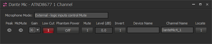
- Peak - indicates when input signal is within 3dB of clipping
- MicMute - indicates when the microphone is locally muted
- Gain - allows selection of input gain level for the microphone
- Low Cut - adds a highpass filter at 80Hz on the microphone signal
- Phantom Power - only available on the ATND8677, turns on 12VDC phantom power to the attached microphone
- Mute - mutes the microphone signal. This mute is independent of the microphone's local mute function.
- Level - digital level control of the microphone signal
- Invert - inverts the phase of the microphone signal
- Device Name - shows the hostname of the Dante transmitter device
- Channel Name - shows the name assigned to this channel, can be changed via the Property Sheet of the input block, or from Dante Controller software
- Locate - when activated, the LEDs on the microphone will flash to allow for easy identification of the microphone
Dante Controller software
Dante Controller software is required to route the microphones to the Tesira system. It can be downloaded from http://www.audinate.com. Further information can be found on the Audinate website under Support > Documentation > User Guides.
The "Device Name" field in a Dante Mic input block will display "<disconnected>" until a valid Dante microphone has been routed to that input via Dante Controller software.
Maximum connected mics
- Each DAN-1 card will accept up to 32 channels of AT mics (a maximum of 32 input flows are allowed per DAN-1). Each Server-IO supports up to (2) DAN-1 cards, allowing for a maximum of 64 AT mics per chassis.
- Each ForteDAN will accept up to 32 channels of AT mics (a maximum of 32 input flows are allowed per ForteDAN).
The AT mic input blocks will compile to Dante input channels 33-64 in the Tesira DAN-1 and input channels 1-32 in the ForteDAN.
Generic Dante input blocks can be utilized alongside the AT mic blocks for a total of 64 channels of Dante input per card, noting that the 32 flow limitation must still be respected. No more than 32 discrete devices can talk to a DAN-1 card, as each device will have at least 1 flow containing at least 1 channel, and the DAN-1 (Brooklyn II) supports 32 x 32 flows.
More information on Dante flows can be found at https://support.biamp.com/General/Networking/Dante#Flows:_unicast_and_multicast
Advanced configurations
Often, configuring the microphones in one of the simple muting modes is sufficient. However, there are some cases where more customized behavior is desired. Below are some examples of common advanced techniques to use these microphones in real situations. All of these examples utilize the Dante Mic block in "External" mode, which allows the mute state to be controlled via logic. This is typically required for customized applications, whereas the other modes are for simpler applications.
Mic muting with AEC
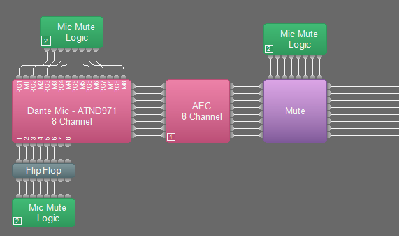 When microphones are used in teleconferencing and videoconferencing scenarios, they must be put through Acoustic Echo Cancellation (AEC) processing. When mics are put through AEC processing and are also being dynamically muted and unmuted, it is preferable to mute the mic signal after it has gone through the AEC processing, so that the AEC processing can continue to listen to the microphone while it is muted. This allows the AEC processing to stay converged on the echoes and ensures that no echoes will be heard when the mic is unmuted.
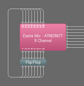
To set up this configuration, create a Dante Mic block with the Microphone Operational Mode set to "External - logic inputs control Mute". Set the LED Logic Inputs to "Logic input toggles red and green LEDs", and ensure that Logic Outputs are enabled. Connect the mic signals through your AEC processing (which requires SEC-4 cards), and then to a Mute block with Control Inputs enabled. The logic outputs on the Dante Mic block need to go to a Flip Flop gate to convert them from momentary signals to toggle signals. The output of the Flip Flop drives the logic inputs on the Mute block, and also drives the Red/Green LED logic inputs (RG1, RG2, etc.) on the Dante Mic block. See the screenshot above for an example of what the configuration for this system would look like (click to enlarge). The green blocks are Split Pass-Through blocks, which are optional.
Any microphone mutes all microphones
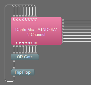 Sometimes it is preferable to not allow independent muting. That is, if any mute button is pressed on any mic, then it toggles the mute state of all mics. This is easy to achieve with logic.
To set up this configuration, create a Dante Mic block with the Microphone Operational Mode set to "External - logic inputs control Mute". Set the LED Logic Inputs to "None, LEDs always follow device Mute status", and ensure that Logic Outputs are enabled.
The logic outputs on the bottom of the Dante Mic block must pass through an OR Gate, then a Flip Flop gate, and then back up to the Muting logic inputs on the top of the Dante Mic block. See the screenshot to the right for an example of what the configuration for this system would look like (click to enlarge).
Integrate with control system
When the audio system includes a control system that is able to mute and unmute the microphones, it is important to ensure that the control system remains properly synchronized with the system. There are a number of different ways to integrate a control system:
Only control system can mute
 In this example, only the control system is allowed to mute the mics. The mute switch on each mic is deactivated, and the LED on each mic shows the current mute status. To set up this configuration, create a Dante Mic block with the Microphone Operational Mode set to "External - logic inputs control Mute". Set the LED Logic Inputs to "None, LEDs always follow device Mute status". You can also disable Logic Outputs (optionally). Connect a Logic State block to the muting Logic Inputs on the top of the Dante Mic block (labeled M1, M2, M3, etc.). Program the control system to control the Logic State block to mute and unmute each mic. When the Logic State is turned on, the mic will be muted, and the mic will be unmuted when the Logic State is turned off. See the screenshot to the right.
Control system and mute switch can mute
 If the desired operation of the system includes the ability to mute from the microphone and mute from the control system, then the system needs to be configured a bit differently. To set up this configuration, create a Dante block with the Microphone Operational Mode set to "External - logic inputs control Mute". Set the LED Logic Inputs to "None, LEDs always follow device Mute status". Ensure that Logic Outputs are enabled. Connect the Logic Outputs of the Dante Mic block to a Flip Flop gate (to convert them from momentary to toggle signals), and then connect the Flip Flop gate to the Logic Inputs on the top of the Dante Mic block. Program the control system to control the Flip Flop gate to mute and unmute each mic. When each Flip Flop is turned on, the mic will be muted, and the mic will be unmuted when the Flip Flop is turned off. See the screenshot to the left.
Individual mute from mic, global mute from control system
A common scenario is to allow each microphone to mute and unmute itself from the mic mute button, and only allow the control system to globally mute and unmute all microphones. This can be accomplished using the exact same configuration as described in the example immediately above ("Control system and mute switch can mute"). The only change will be that two presets will need to be created, one to turn all of the Flip Flops on (the "mute" preset), and another to turn all of the Flip Flops off (the "unmute" preset). And, instead of programming the control system to control the Flip Flop gate directly, the control system should be programmed to recall each of the two presets.
Mute lockout
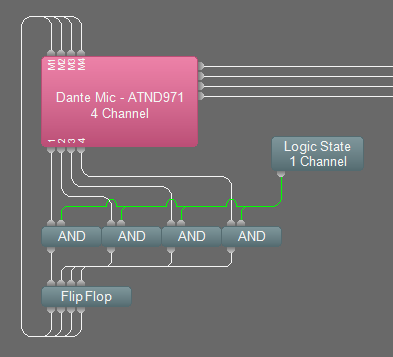 There may be some cases where the microphone mute buttons must be dynamically deactivated. In other words, the control system can temporarily "lockout" the microphone mute switches so that they no longer can change the mute status. To set up this configuration, create a Dante block with the Microphone Operational Mode set to "External - logic inputs control Mute". Set the LED Logic Inputs to "None, LEDs always follow device Mute status". Ensure that Logic Outputs are enabled. Connect the Logic Outputs of the Dante Mic block through AND gates and Flip Flop gates as shown in the screenshot to the right. Connect a Logic State block to the AND gates as shown in the screenshot (the wires are green for ease of viewing). Program the control system to control the Logic State block. When the Logic State block is off, the mic mute buttons will be locked out (i.e. deactivated). When the Logic State block is on, the mic mute buttons will function again.
Long press mutes all mics
 Another popular trick is to perform a different function when the mic mute button is held down for a few seconds. In this example, the mics will be configured to toggle their mute state normally when the mute button is pressed briefly, but when the mute button is held down for 2 seconds, all mics will mute.
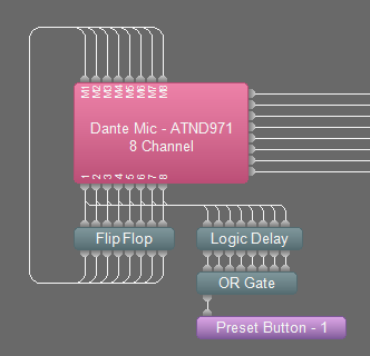
To set up this configuration, create a Dante block with the Microphone Operational Mode set to "External - logic inputs control Mute". Set the LED Logic Inputs to "None, LEDs always follow device Mute status". Ensure that Logic Outputs are enabled. Connect the Logic Outputs of the Dante Mic block to a Flip Flop gate (to convert them from momentary to toggle signals), and then connect the Flip Flop gate to the Logic Inputs on the top of the Dante Mic block. Then, also connect the Logic Outputs of the Dante Mic block to a Logic Delay block, through an OR gate, and then to a Preset Button block. See the screenshot above.
Open the Logic Delay block, and set the "On Delay" of each channel to 2000ms. Leave the "Off Delay" at 0ms. Create a preset that turns all of the Flip Flop channels on. Open the Preset Button block, and load that preset into it. That way, whenever any of the mics holds down its button for more than 2 seconds, the preset will get recalled and all mics will mute.