Connecting a beyerdynamic Classis BM 52 RC to an EX-LOGIC
One popular application for the Tesira EX-LOGIC is to interface with conferencing microphones that feature mute switches and LED indicators. This article describes how to physically connect a beyerdynamic boundary microphone to a Tesira EX-LOGIC expander.
Goal
After completing the steps in this article, you will be able to connect a beyerdynamic boundary microphone to a Tesira EX-LOGIC. This will allow your Tesira configuration to mute and unmute the connected microphone remotely and it will also allow the switch on the microphone to control functions within your Tesira configuration (like camera control or override/priority logic functions).
The microphone uses phantom power to power its LED and logic circuit, so no external power supply is required.
Pinout
The BM 52 RC microphone facilitates a mute switch and a single-color LED. It comes with a 5-pin XLR connector, with the following functions assigned to each pin:
| Pin | Function |
|---|---|
| Pin 1 (br) | Ground |
| Pin 2 (rd) | Audio (+) |
| Pin 3 (bl) | Audio (-) |
| Pin 4 (wh) | Switch output |
| Pin 5 (bk) | LED input |
Wiring
An EX-LOGIC has 16 Logic I/O connections. Each Logic I/O can either be used as an input or an output (but not both), and input/output status of each terminal is determined by the Tesira programming. The diagrams in this article arbitrarily show logic inputs as channels 1-8, and logic outputs as channels 9-16, but the Tesira programming can define the inputs and outputs differently.
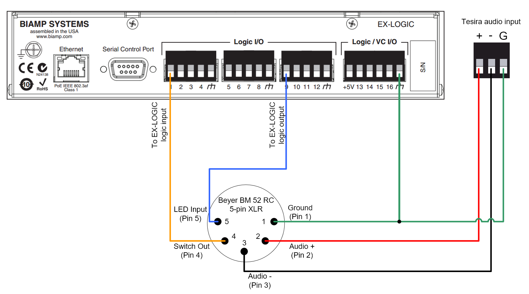
5-pin XLR
The diagram below shows how to connect a beyerdynamic BM 52 RC boundary microphone with a 5-pin XLR to an EX-LOGIC.
Mic options
Operation
The DIP switch located at the bottom of the microphone allows you to select between remote control operation only or the microphone button and remote operation (remote and internal control)
The desired operation mode is set by the right hand rotary switch at the bottom of the microphone.
• Position ON/OFF: The microphone is switched on or off by pressing the push button on the microphone.
• Position PTT: The microphone is switched on as long as the button is pressed.
• Position PTM: The microphone is switched off as long as the button is pressed (cough button).
In all positions the LED indicates the activation of the microphone.
Note that the internal microphone signal flow cannot be bypassed. A mute condition triggered from internal or external operation, will always interrupt the audio signal flow. This should be considered in applications with Gating Auto Mixers and Acoustic Echo Cancelling inputs.