Connecting an Earthworks IML or IMBL to an EX-LOGIC
One popular application for the EX-LOGIC is to interface with conferencing microphones that feature mute switches and LED indicators, and Earthworks is a leading manufacturer of such microphones. This article describes how to physically connect an Earthworks IML-series or IMBL-series microphone to a Tesira EX-LOGIC.
Note that even though this article shows diagrams for only the EX-LOGIC, the logic I/O terminals that are built into Tesira servers and TesiraFORTÉs can be used for the same purposes as an EX-LOGIC.
Goal
After completing the steps in this article, you will be able to connect an Earthworks IML3, IML6, IML10, IML12, or IMBL30 to a Tesira EX-LOGIC. This will allow your Tesira configuration to control the LEDs on the microphone, and it will also allow the mic's mute switch to control functions within your Tesira configuration (like mic muting).
Pinout
The Earthworks mics have a ribbon cable that is connected to either a small Phoenix connector or an RJ45 connector for the LED and touch switch connections. The pinouts for the Phoenix and RJ45 connectors are as follows:
|
|
Wiring
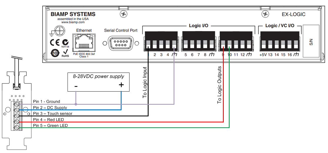
The audio conductors on the microphone will connect to the audio inputs on the Tesira device like a typical microphone. The LED and switch conductors will connect to the EX-LOGIC. The LED conductors connects to logic outputs, and the Touch sensor connects to a logic input.
Each IML/IMBL uses three I/O terminals on the EX-LOGIC, meaning that a maximum of five microphones can be connected to a single EX-LOGIC. The diagram below shows a typical wiring scheme for a single IML or IMBL-series microphone:
Logic control
The touch sensor input will create a normally-high logic signal, and it will go low when the sensor is touched. To reverse that behavior and make it normally-low, open the corresponding Logic Input block and activate the Invert button (or, run the logic signal through a NOT gate).
The LED outputs will light up the LED when a low logic signal is sent to the corresponding output, and will turn them off when a high logic signal is sent. To reverse that behavior such that the LEDs turn on when the logic is high, open the corresponding Logic Output block and activate the Invert button (or, run the logic signal through a NOT gate).
Further reading
- Once the device is physically connected to the EX-LOGIC, you'll need to program it. See EX-LOGIC programming for more information.
- Muting microphones with logic