Tesira redundancy and failover
Tesira Server AVB devices supported a native DSP failover redundancy option through the 3.15 software/firmware release. Only the Tesira Server AVB hardware supported redundancy. Native failover redundancy was removed from Tesira as a feature in versions 3.16 and newer.
To enable Server redundancy, a dedicated hard link was required on the GPIO ports between a matched pair of Server processors. If the Primary device failed then the Secondary device would take over, with Control data and AVB streams automatically routed through the Secondary device. Systems which use this form of Server redundancy cannot be brought up to any later FW version (3.16 or higher) without losing the redundancy functionality.
This article presents a process for creating an alternative DSP failover method through manual programming.
DSP failover
Tesira software utilizes partitions - effectively these allow the creation of standalone sub-systems within the larger Tesira DSP configuration. Typically partitions are used to configure separate rooms or areas within a building to allow service or modification of some areas while others are in use.
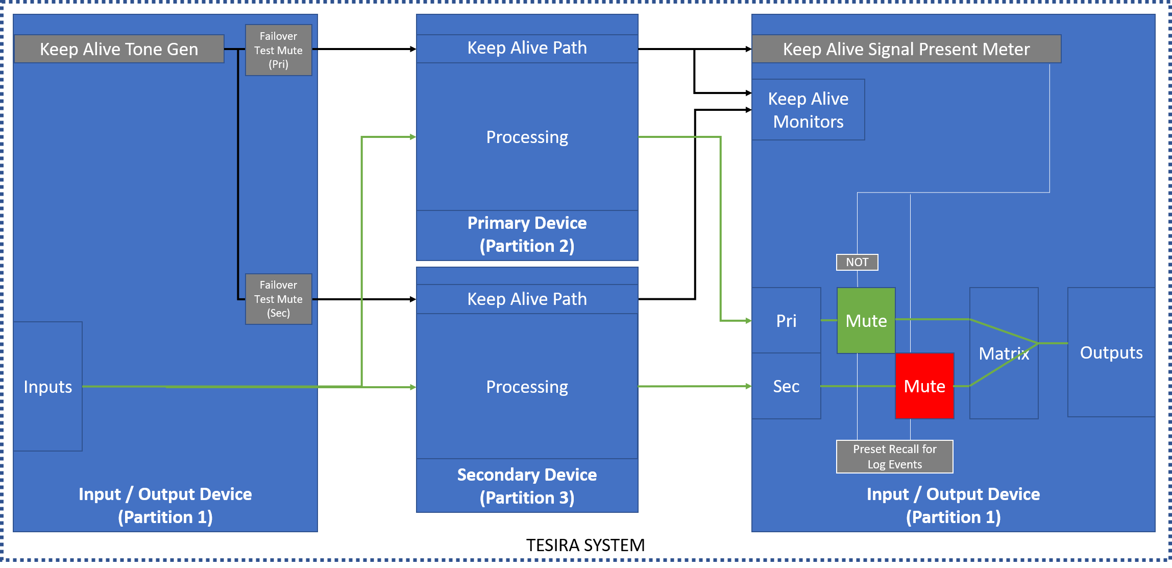
For the purposes of processing redundancy, partitions can be used to isolate DSP devices. Input signal from an input / output DSP device can be shared across partitions to one or more other DSP devices for processing, then routed back to the input / output DSP device for output. A keep-alive tone from the input / output DSP is used to ensure that there is an active pathway between devices.
Audio content enters the input / output DSP and is always routed to both the "primary" and "secondary" devices, which are loaded with matching signal paths. In normal operation the "primary" DSP signal path is used. If the keep-alive tone fails to pass through the "primary" device the "secondary" signal path is selected in the output device. When the keep-alive from the "primary" device re-appears then the signal path is switched back to it.
A signal present meter in the input / output DSP is used to monitor the keep-alive tone. The signal present meter's logic output is used to trigger a mute / unmute in the signal paths from the "primary" and "secondary" devices.
The keep alive tone generator, signal present meter, logic blocks, mute state, and all partition connections (send and receive blocks) must be set as "fixed in unit" within the input / output DSP device. If a "primary" or "secondary" device falls offline this isolates the lost audio path within the missing device. (In this application it is generally recommended that all DSP blocks be manually set as "fixed in unit = true" for their respective DSP devices to ensure they are compiled to the expected device.)
Tesira uses implicit AVB (automatically routed between devices) to pass audio between devices, so all processors must have an AVB card for this scenario to be employed with minimal effort. This same path failover technique can be achieved with Dante or CobraNet devices with additional manual routing steps.
Logging failover events
Tesira creates an event in the system logs whenever a preset is recalled. The preset does not need to actually trigger any action in the file, simply creating an empty preset and recalling it is enough to generate a log entry. A preset block recalling 2 empty presets named "Pri Active" and "Sec Active" can be added to the file to be triggered when the signal present meter logic changes state. This allows forensic tracking of failover events. The preset recall block must be set as "fixed in unit" within the input / output DSP. Date and time on all devices should be set to follow an NTP server to keep log dates synchronized.
Control systems
To maintain control functions in a failover system topology it is important to maintain parallel control paths to elements in both the "primary" and "secondary" partitions for control synchronization. For example, the same room volume level control needs to be controlled in both the "primary" and "secondary" partitions to ensure smooth behavior in failover.
In the event of a failover to the "secondary" DSP the parallel control is perfectly synchronized with the state of the control in the "primary" DSP, ensuring smooth continuity of system operation. Changes made to control states while in failover are effected in the "secondary" DSP only, as the "primary" DSP is offline.
When the "primary" DSP is recovered the system must be manually toggled back to the "primary" path and 3rd party control states recalled to a default setting to re-synchronize the "primary" and "secondary" DSP control states. This ensures that all controls are aligned in both the "primary" and "secondary" DSPs. Recovery from the failover condition would normally be done at a time when the system is not in use for any critical application to ensure there are no interruptions of events in progress, as level control or signal path changes may be recalled during the recovery reset.
We recommend the control system maintain unique command processor connections to each DSP device to monitor the online status of each DSP.
- Keep alive AVB stream audio activity through the "primary" and "secondary" DSP devices can be monitored in the input / output DSP.
- Control IP communications with each unique Tesira device allow device monitoring by the control system. This concept is discussed further in this article.
- Parallel control data is passed to the targeted control points in the "primary" and "secondary" DSP devices.
- If a device fails and is recovered, the control system must refresh the current control states to both the recovered device and the failover device, prior to allowing it to pass audio traffic. This is done manually at a time which is convenient to the users of the facility.
Note: Tesira Server and Server-IO SNC-1 and SNC-2 network cards have Primary and Secondary control ports. The Secondary control port is not utilized by either model of Tesira.
Network cabling topologies
Tesira supports several network cabling topologies:
- "Single cable" networks use the AVB primary ports of the Tesira DSP devices to pass both control and AVB data, the control port is left disconnected.
- "Converged" networks connect the control ports and AVB primary ports to a common network.
- "Separated" networks have a unique control network and a unique AVB network. The 2 networks do not touch.
"Single cable" is the preferred topology since it allows for monitoring a single point of failure for failover.
AVB redundancy
Certain Tesira devices support AVB stream redundancy. These devices have an AVB Primary and an AVB Secondary port. Duplicate AVB streams are always automatically created and presented on both ports when these devices are programmed.
Best practice is for redundant AVB streams to be on separate physical networks to prevent outages due to link or switch failure, but they can be placed on the same network for testing. If both AVB Primary and AVB Secondary are connected to a common network the total AVB stream count is doubled within the AVB switch as each stream has a Primary and Secondary version on the network.
In systems using single cable network connections control data is transmitted through the AVB Primary port only, so control traffic will be lost if a device loses its AVB Primary link, but audio will continue to flow across the AVB Secondary. Control traffic will reconnect automatically once the AVB Primary is re-established.
Streams from an AVB Secondary port cannot connect to talkers or listeners on AVB Primary ports (nor to any Tesira device with only one AVB port) and vice versa.
AVB redundancy is only supported on those Tesira devices with AVB Primary and Secondary ports.
- Tesira Server
- Tesira Server-IO
- Tesira AMP-4175R, AMP-4300CV, AMP-4350R, and AMP-8175R
- TesiraXEL 1200.1 and 1200.2 amplifiers (when configured for AVB Primary and Secondary)
AVB streams are identified by the AVB talker port's MAC number plus stream ID number. Redundant AVB stream pairs use the same stream ID number but the AVB Primary and AVB Secondary ports have unique MAC addresses, differentiating the 2 streams.
Explicit AVB connections are supported on the Primary AVB network only. Explicit AVB streams must be manually routed using 3rd party AVDECC software.
See the article AVB Primary and Secondary connections for an in-depth look at this topic.