Tesira GPIO or EX-LOGIC Programming
This article discusses different techniques for interfacing with external devices using logic signals, as well as a brief introduction to some commonly used logic gates. In Tesira, external logic devices can be connected to an EX-LOGIC expander, or to the logic I/O terminals on a SERVER, SERVER-IO, TesiraFORTÉ, or TesiraLUX. The examples in this article assume that an EX-LOGIC is being used, but they are all equally applicable on any of the hardware mentioned above.
These connections are also available on the Tesira Forte X, Tesira XEL, Tesira AMP 8x and 4x series amplifiers.
Basics
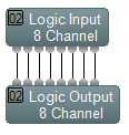
To interface with external devices, simply add Logic Input and/or Logic Output blocks to your Tesira configuration file. Logic Inputs are for devices that are going to affect a change in your Tesira file (like a mute button), and Logic Outputs are for devices that are going to be changed by Tesira (like an LED).
There are only two states that a logic signal can be: high or low (also frequently referred to as on or off, 1 or 0, true or false). The sections below describe how logic signals interact with the Logic Input and Output blocks.
Logic inputs
The logic inputs on an EX-LOGIC are used to detect contact closures from external devices. They are often used to sense closures from external switches or pushbuttons. When a switch connected to a logic input is closed (shorted to ground), a low logic signal is generated at the corresponding Logic Input block. When the switch is open to ground, a high logic signal is generated. This means that logic inputs are “normally high”; that is, if there is nothing connected to a logic input, it will be generating a high logic signal.
Logic outputs
The logic outputs on an EX-LOGIC are used to trigger contacts to open and close, and can be thought of as being similar to a relay. They are often used to control LED’s or trigger external relays. By sending a logic signal to a Logic Output block, you can change whether that logic output is creating a short circuit to ground or an open circuit to ground. Sending a low logic signal results in a short circuit, and sending a high logic signal results in an open circuit.
Logic Gates
Logic gates can be used to transform logic signals in various ways. To insert a logic gate into your configuration file, select Logic Gate from the Logic Blocks menu on the Object Toolbar, click in your file to insert it, and then select the type of logic gate you want to use. It’s not in the scope of this document to describe all logic gates in detail, but below are a few that are commonly used. For details on other logic gates, consult the Help system in Tesira software.
NOT Gate
A NOT gate is a simple logic gate that inverts the logic signal that it is receiving. In other words, if you send a low logic signal to the input of a NOT gate, it will output a high logic signal, and vice versa.
For instance, if you connect a contact closure button to a logic input on an EX-LOGIC, and that button is normally open (i.e. it creates a short circuit when the button is pushed), then the Logic Input block will be generating a high logic signal when the button is not pushed and the logic signal will go low when the button is pushed. However, you may want the logic signal to be low when the button is not pushed, and high when it is pushed. In this case, a NOT gate is the solution.
Flip Flop Gate
A Flip Flop gate is used to transform a momentary logic pulse signal into a latching (or toggle) logic signal. The Flip Flop gate works by toggling its output signal whenever its receives a low-to-high logic transition on its input. It doesn’t do anything when it receives a high-to-low logic transition. So, the first time it receives a low-to-high transition, it will start sending a low logic signal out of its output.
Logic State
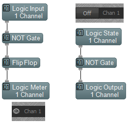
A Logic State block is a logic block which generates a logic signal. It will generate a low logic signal if its “Set” button is disengaged, and it will generate a high logic signal its “Set” button is engaged. A common use for a Logic State block is to generate a logic signal and send it directly to a Logic Output block. This would allow you to manually control whether a logic output is opened or closed, and is useful for testing purposes too.
Logic Meter
Logic Meters are a very useful troubleshooting tool when programming an EX-LOGIC, because they allow you to view the state of a logic signal at any point in your logic circuit.
Example Applications
Contact closure button recalls preset
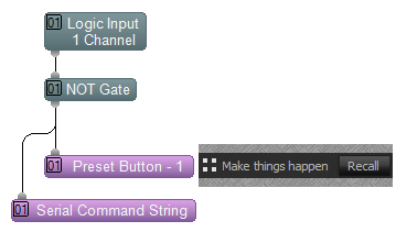 A simple, common application is to connect a contact closure button to an EX-LOGIC, and recall a preset whenever that button is pressed. The key to making this happen is the Preset Button block. This block is triggered by a logic signal and recalls a preset whenever it sees a low-to-high logic transition. To load a preset into a Preset Button block, open the block and choose the desired preset from the drop-down menu. If your contact closure button is normally open, using a NOT gate as shown in the picture to the right will ensure that the preset gets recalled when you push the button down, not when you let it up.
Contact closure button sends a serial string
Also in the picture above, notice that the same contact closure button is connected to a Command String block. A Command String block operates the same way as a Preset Button block, but instead of recalling a preset, it sends a custom string out of the RS232 port on the unit. This is useful for notifying a control system of an event that has happened. You can also use a Command String block to send hex characters by preceding the two-digit hex code with a tilde character (~). In Tesira, Network Command String blocks are also available to send messages out of the network port instead of the serial port.
Momentary contact closure mutes and unmutes a mic
The Mute block has the capability of controlling its mute buttons via logic signals. When dropping the Mute block into your file, ensure that the “Control Inputs” check box is checked. This will enable logic inputs on the block. If the logic input for a channel receives a high logic signal, it will mute the mic. If it receives a low logic signal, it will unmute the mic.
More often than not, a microphone mute switch is a momentary switch. That is, the switch is closed while you’re pushing it down and open when you let it up. If you connected a momentary switch to an EX-LOGIC, and then connected a logic signal from the Logic Input block directly to the Mute Control block, it would only unmute the mic when you push the button down and would mute the mic as soon as you release the button (i.e. a push-to-talk button). If you connected the logic signal through a NOT gate and then to the Mute Control block, it would mute the mic only while the button is held down (i.e. a push-to-mute button). More commonly, users expect a toggle functionality where the mic will toggle on and off each time they press the button. They might also expect the LED on the mic to turn on when the mic is live and turn off when the mic is muted.
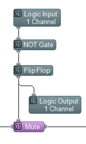
The logic circuit in the picture to the right shows a common way to make this happen. The Flip Flop gate transforms the momentary logic signal to a latching signal, and its output controls both the muting of the microphone and the state of the LED.
Note that a NOT gate is needed before the Flip Flop so that the Flip Flop will change state when the button is pressed rather than when the button is released.
Refresh Connection State
If an EX-LOGIC loses power and then reconnects to Tesira the state of the logic connections is not automatically refreshed. So if an active Logic State were tied to an LED driver block, the LED would not light up on power recovery. We can cause the EX-LOGIC to refresh its state by sending a communications pulse to it.
You can simply tie a signal generator to either a Logic Out or to a serial Command String block to generate data to the device. This will generate traffic to the device to update all Logic states on the box after a power cycle.
Optionally you can physically link the Logic Out port to a Logic In port on the same EX-LOGIC to create an active state report for the box.
