Video network design
Biamp's Tesira family forms a powerful networked media system, and AVB is the ideal media networking protocol suite to provide the system's backbone for both audio and video signals.
AVB is part of the 802.1 Ethernet standards. Time synchronization, quality of service, bandwidth management, VLANs, automatic address multicast allocation and selective multicast forwarding are all part of the AVB package, automatically protecting your critical AV traffic while at the time holding bandwidth in reserve to keep the rest of your system functioning as expected.
Careful network design consideration will give your media system a robust and reliable transport, and all the bandwidth it needs.
Key AVB components
gPTP: keeping time
IEEE802.1AS, also known as gPTP, Generalized Precision Time Protocol, is the heart of the time-aware AVB network. Every link is checked and synchronized individually, improving accuracy, synchronization time, and robustness when compared with other protocols.
MSRP: reserving and managing bandwidth
Multiple Stream Registration Protocol provides bandwidth management and access control on each media link. When an AVB listener requests an audio or video stream from an AVB talker, MSRP reserves the required end-to-end bandwidth after first checking its availability. And because MSRP puts a cap on how much bandwidth AVB is permitted to reserve, MSRP protects your non-media traffic just as it protects your audio and video.
MVRP: administering VLANs
AVB will automatically assign your AV data to a dedicated VLAN (VLAN 2 by default). Multiple VLAN Registration Protocol (MVRP) is how the switches administer this process.
FQTSS: QoS and traffic shaping
FQTSS, Forwarding and Queuing for Time-Sensitive Streams, manages quality of service and traffic shaping. By releasing AVB packets in guaranteed slots at timed intervals, AVB traffic-flow is both reliable and smooth, even across large networks. Traffic shaping not only benefits AVB, however. Irregular and bunched media traffic causes delays to all traffic, while smooth media traffic ensures that non-media bandwidth stays smooth too.
Supported platforms
TesiraLUX is only supported on Avnu-certified switch platforms. See the List of AVB-capable Ethernet switches for specific models supported.
Not all AVB switches are necessarily appropriate for TesiraLUX video streams, since AVB video streams have significantly higher bandwidth requirements than AVB audio streams. It is critical to ensure that network switches have adequate port bandwidth, uplink bandwidth, and backplane bandwidth to support the desired quantity and type of AVB video streams. See the section below on bandwidth requirements for more details.
Bandwidth requirements
The higher bandwidth requirements of networked video need greater consideration than those of networked audio, particularly networks consisting of multiple switches, in which the bandwidth requirements of inter-switch uplinks must be evaluated.
Endpoint bandwidth requirements
TesiraLUX supports AVB over a copper network connection up to 1Gbps and over an optical fiber SFP+ network connection up to 10Gbps. However, AVB is generally limited to utilizing no more than 75% of a network link's bandwidth. Therefore, a 1Gbps copper connection can support AVB streams with bandwidths up to 0.75Gbps, and 10Gbps fiber connections can support AVB streams with bandwidths up to 7.5Gbps.
The control panel of the TesiraLUX IDH-1 shows the maximum bandwidth the device will transmit to the network. Double click on the IDH-1's block in the configuration, then select the tab To Network.
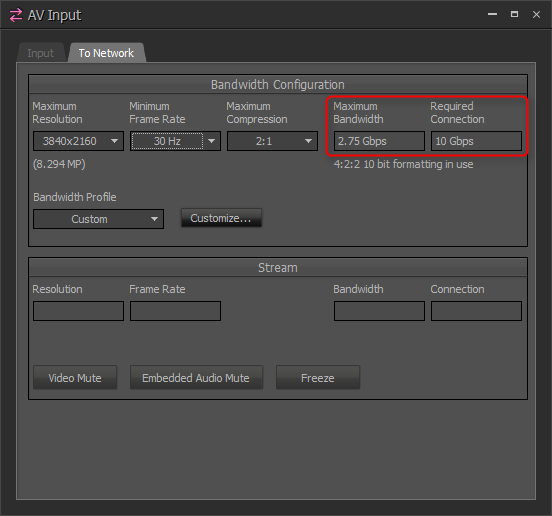
Figure 1 - IDH-1 control panel, bandwidth and connection information
The Required Connection field will show whether a 1Gbps (copper RJ45) or a 10Gbps (SFP+ fiber) network connection is required for the chosen settings. The Maximum Bandwidth field will show maximum bandwidth that the IDH-1 will transmit to the network given the selected resolution, frame rate, and compression.
Additionally, an XML table of the system's AV bandwidth settings can be exported from the File menu.
Uplink bandwidth requirements
Uplinks are the connections between switches. Often the bottleneck points in the network's bandwidth, they are worthy of careful consideration.

Figure 2 - Uplink bottleneck
Calculating uplink bandwidth requirements
The bandwidth requirement for an uplink can be calculated in the following way.
Look at the IDH-1 devices on one side of the uplink, and identify which of those will be required to transmit to OH-1 receivers on the other side of the uplink.
Next, identify how many of those IDH-1 will be required to transmit to the other side of the uplink simultaneously. If not all of the IDH-1 will be required to transmit at the same time, ignore any that will transmit lower bandwidth streams. This will allow the worst case figure to be calculated.
Finally, add up the values shown in the Maximum Bandwidth fields of those IDH-1 devices. This will be the bandwidth requirement of the uplink in that direction.
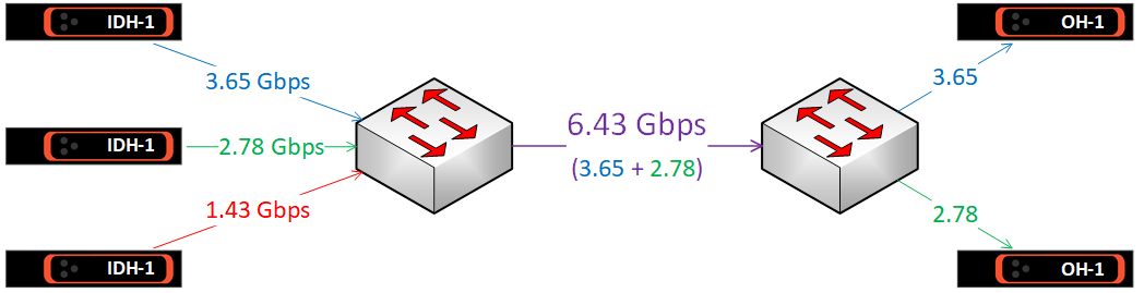
Figure 3 - Uplink bandwidth
To calculate the bandwidth required across the uplink in the other direction, do the same calculation for the IDH-1 devices on the other side of the uplink. AVB audio bandwidth requirements are often small in comparison to video bandwidth requirements, but be sure to consider this too if the system utilizes a lot of AVB audio.
Uplink options
Many network switches will have more than one type of port, with the faster ports intended as uplinks to other switches. A switch on which the majority of ports are 1Gb may have a small number of 10Gb ports, and a switch with mostly 10Gb ports may have some 40Gb ports. See the supported platforms section for more details.
Typical copper cable options are 1Gb and 10Gb, although 2.5Gb and 5Gb are becoming more common. The typical Fiber option is 10Gb (using SFP+ fiber modules) but 40Gb is also available on higher-end models (using QSFP+ fiber modules).
Switches featuring higher-capacity ports are usually more expensive than switches with lower-capacity ports. An alternative is to combine two or more lower-capacity ports together into a virtual port. Called Link Aggregation, this feature allows two or more links to be bonded together into single logic link known as a LAG (a Link Aggregation Group). See the section LAGs below.
Bandwidth management
Multicast management is automatic
Multicasting allows one transmitter to send data to many receivers, which has obvious benefits for networked AV. However, without additional management, multicast traffic on an Ethernet network will behave in the same way as broadcast traffic: it will flood to every port on the VLAN, quickly wasting bandwidth. This is not the case for AVB.
AVB streams are multicast by default, but because AVB stream reservation is demand-driven, the switches will forward each stream only to the ports where a listener (an AVB receiver) has requested it. In other words, AVB provides selective multicast forwarding with no network configuration required.
If no AVB listeners request an AVB talker's advertised stream, the talker will stay silent. If one listener requests the stream, the talker will send a single stream and the network's switches will forward it only to that listener. If two or more listeners request the stream, the talker will still transmit a single stream, and the network's switches will forward it directly to those listeners and nowhere else.
Limiting AVB traffic on an uplink
Uplinks are usually a network's bottlenecks, and it's not only the requirements of AV data that need to be considered.
As mentioned above, AVB is usually permitted to reserve up to 75% of the bandwidth on any network connection, i.e. AVB has priority over that 75% but cannot reserve any more than 75%. Uniquely amongst AV protocols, once the reservation limit has reached, the network will refuse any new streams requesting access to the network.
Less commonly known is that 75% is simply the default setting. The user can adjust this reservation limit individually for each switch port. This feature gives the system administrator absolute and precise control over how much bandwidth is allocated for AVB and how much bandwidth is reserved for non-media network traffic.
Limiting AVB traffic on Extreme switches
Extreme AVB switches can be configured to limit the bandwidth allocated for AVB stream reservation on a per-port basis. Termed the delta-bandwidth, the parameter is simply a percentage of the link that may be reserved for AVB traffic.
The default value for delta-bandwidth is 75, meaning 75%, and altering the delta-bandwidth for a given port will change the maximum percentage of the port's bandwidth that can be used for AVB. The setting affects the egress behavior of the port, i.e. the traffic exiting that port and being sent to the device at the other end of the link. This gives a very granular control, as the same link could have different limits set for each direction.
The command is:
configure msrp ports <port number> traffic-class <A or B> delta-bandwidth <percentage>
(Note: class B traffic is not used by Biamp.)
Example: a switch has a 10Gb uplink to the next switch on port 24, and we want to allow the switch to assign no more than 50% of the uplink's bandwidth to AVB. The command is:
configure msrp ports 24 traffic-class A delta-bandwidth 50
The switch will now send no more than 5Gbps of AVB data across the uplink, and the remaining 5Gbps will be reserved for non-AVB traffic. To restrict the incoming AVB bandwidth on the same link, log into the switch at the other end of the uplink and enter the same command.
Tesira software has an AV Input block bandwidth configuration that can be configured up to 75% of the link or capped at a lower number. This does not change the limits in the switch nor does it impact uplinks between switches. The delta-bandwidth needs to be configured on the uplink ports of the switches.
Warning! Some bandwidth must always be preserved for non-AVB traffic, even if it is just for Tesira's discovery and control traffic. Biamp recommends leaving at least 10% delta bandwidth for non-AVB traffic on uplinks (15% for 1GB uplinks). This number should be higher if the network's resources must be shared with other systems.
More bandwidth using LAGs
Link aggregation, also known as load sharing, is a method of grouping links together. It provides a simple and inexpensive way to increase bandwidth (or provide link redundancy - see section Network Resiliency).
It works by aggregating two or more physical switch ports into a single logical port, commonly known as a LAG (Link Aggregation Group). The LAG will have the combined bandwidth of its member ports, but, once the LAG is set up, it can be configured in the switch as if it were a single port.
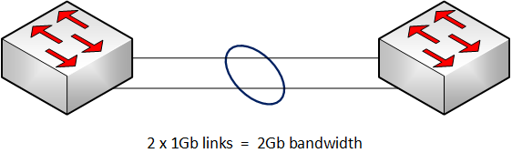
Figure 4 - Link Aggregation Group to Increase bandwidth
LAGs on Extreme switches
Requirements
- All member port must have the same speed and duplex. For example, you cannot make a LAG using a combination of 1Gb and 10Gb ports.
- Copper and fiber ports can be combined into a LAG, provided the ports are of the same speed and duplex.
Creating a LAG
To avoid creating a broadcast storm, the LAG must be created before the member ports are connected (or enabled).
The basic command to create a LAG on an Extreme switch is:
enable sharing <local port> grouping <member port list> lacp
Example: create a LAG with the master port number 23 and the member ports 23-24. The command is:
enable sharing 23 grouping 23-24 lacp
The LAG must be created in the same way at both ends of the uplink, so the correct commands must be entered into each switch before the LAG can be used.
Note: adding "lacp" to the command enables Link Aggregation Control Protocol, which is recommended as it automates some management of the LAG. For example, if any of a LAG's member ports are wrongly connected, a broadcast storm could result. LACP will detect this condition and prevent the LAG from operating if wrongly connected.
See the Extreme user guide for more information on creating and managing LAGs.
Bandwidth management on the LAG
When first created, the LAG will be configured for redundancy rather than increased bandwidth. For example, if a LAG comprises two links each of 1Gb, the LAG's AVB bandwidth will still be 750Mb (75% of a single 1Gb link), but the LAG's two links will provide redundancy should one link fail (see section: Network Resilience).
To configure a LAG for increased AVB bandwidth a further command must be added. The command is:
configure msrp sharing port <port> bandwidth cumulative <percentage>
To allow the full amount of member link to be allocated to AVB (up to the delta bandwidth) set the percentage to 100.
Example: A LAG with 3 x 1Gb member links, its delta-bandwidth set to the default value of 75% and its cumulative bandwidth set to 100%.
Total LAG bandwidth = 3 Gb
LAG AVB bandwidth = 2.25 Gb
For a more balanced trade-off between resiliency and bandwidth, other percentage values can be used. See the Extreme user guide for more information.
To return a LAG to redundancy mode, the command is:
configure msrp sharing port <port> bandwidth single-port
Stream size limit on a LAG
There is one important limitation to consider when using AVB on a LAG: a single AVB stream must be carried wholly on a single link. In other words, an individual AVB stream cannot be split between a LAG's member ports. This has two implications when running AVB streams over a LAG:
- A single stream's bandwidth cannot be larger than the maximum AVB bandwidth of each individual member link.
- Unallocated bandwidth on a LAG member port cannot be combined with the unallocated bandwidth of other member ports to provide for a larger stream; it can only be allocated on that port to a stream of equal or lesser bandwidth.
When assessing LAG bandwidth, therefore, stream size must be taken into consideration, not just the total AVB bandwidth and the total LAG bandwidth.
Example: a LAG with two member ports each of 1Gb, the delta-bandwidth set to the default value of 75%, and the cumulative bandwidth set to 100%.
Total LAG bandwidth: 2 Gbps
Total AVB bandwidth: 1.5 Gbps
Max. AVB stream size 0.75 Gbps (750 Mbps)
Max. streams if stream size is 376-750 Mbps 2 streams
Max. streams if stream size is 251-375 Mbps 4 streams
Max. streams if stream size is 188-250 Mbps 6 streams
Max. streams if stream size is < 187 Mbps 8+ streams
Note: this is a simplified example for illustration only. No consideration has been given to the additional streams used for audio or Tesira synchronization.
Network resiliency
Hope for the best and prepare for the worst.
A network can be made tolerant to faults in a number of ways: use quality components, ensure that cables are installed to specification and tested, and ensure that cable terminations are performed correctly and tested. It is also possible to design and configure a network such that it can self-heal if a component fails.
Redundant power supplies
Many high-end network switches can accommodate two power supplies, one providing backup should the other fail. The two PSUs can even be connected to separate power supply systems for even greater fault tolerance.
Fault-tolerant connections
A LAG works by aggregating two or more physical switch ports into a single logical port, commonly known as a LAG (Link Aggregation Group), and the LAG will have the combined bandwidth of its member ports.
As noted in the bandwidth section above, LAGs can be used for fault tolerance as well as increased bandwidth. Because the two switches will be connected with more than one cable, the uplink between the switches has redundancy. How much redundancy will depend on how the LAG is configured.
When first created, a LAG is by default configured for AVB redundancy. The AVB bandwidth of each additional link will not be available for extra streams, instead providing backup AVB bandwidth should another link fail.
See the section above Creating a LAG.
A network of two switches should use a LAG rather than RSTP for a redundant connection - a LAG provides extra bandwidth as well as resilience, and has faster healing time.
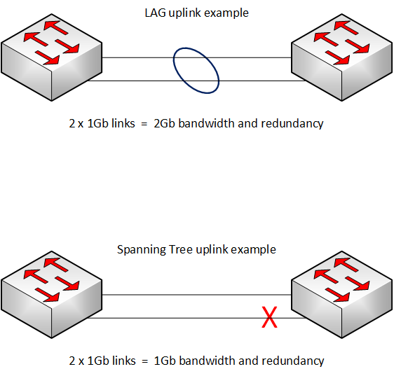
Figure 5 - LAG vs RSTP in a two-switch network
Self-healing networks
There are a number of protocols that can be used in a fault-tolerant network topology. With AVB, the supported protocols are Spanning Tree Protocol (STP, 802.1D) and Rapid Spanning Tree Protocol (STRP, 802.1w). Because Rapid Spanning Tree operates much faster, it is always recommended.
Rapid Spanning Tree Protocol (RSTP)
Rapid Spanning Tree Protocol, as most other protocols of this type, eliminates loops in the network by blocking links, as required, to make a logical network topology that is loop-free. This is useful for preventing a broadcast storm if a loop is created accidentally, but the real usefulness comes from the fact the RSTP is both continuously checking for loops and can unblock links if the cause of the loop is removed.
A loop can be intentionally created in the network to create a self-healing topology. RSTP will block a link to make a logical break in the loop. If, at some point, another link fails, the blocked link will be restored and network connectivity will be restored. To see how it works, see the examples in below in the section fault-tolerant topologies.
RSTP on Extreme switches
While spanning tree and rapid spanning tree are not complicated to set up, the manufacturer's documentation should be followed. Please see the Extreme networks user guide for more information.
Fault-tolerant topologies
Two simple and powerful network topologies for a fault-tolerant network are Ring and Mesh.
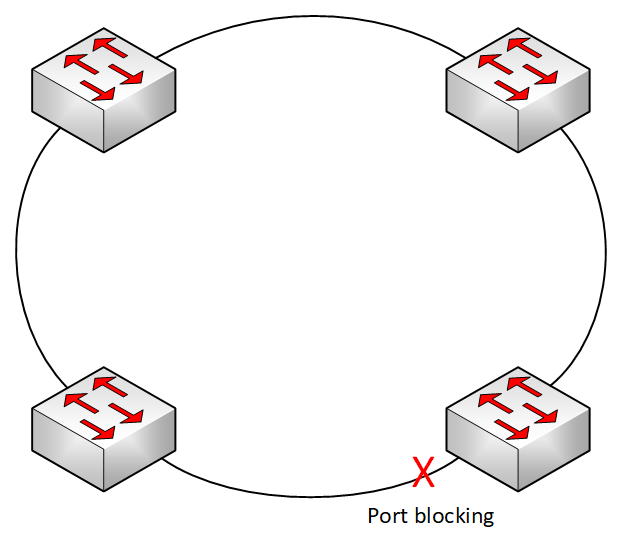
Ring
A ring is a simplest fault-tolerant network topology. Because of this, it is usually the easiest to implement.
| Ring topology using RSTP: normal mode | Ring topology using RSTP: self-healed after cable failure |
 |
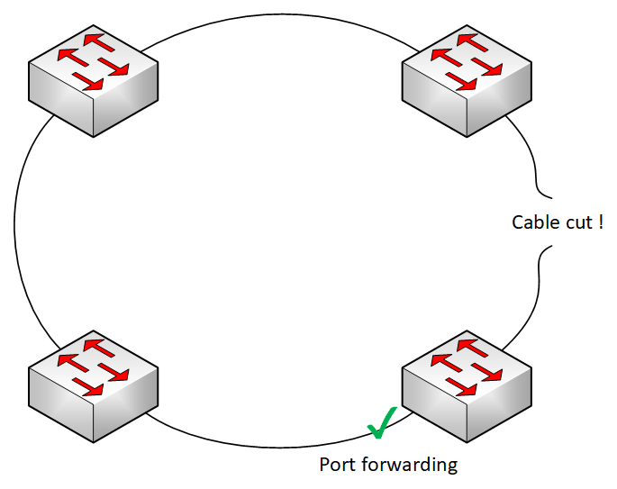 |
Figures 6 & 7 - basic operation of Spanning Tree's fault-tolerance in a ring topology
The propagation delay between any two network endpoints increases with the number of switches between them. We call this the hop count, and the maximum number of switches between any two AVB endpoints is 9.
When spanning tree blocks a port, the traffic that might have passed through that link must go the other way around the ring. In some cases, traffic going from one endpoint to another may have to pass through every switch in the ring.
Therefore, in a ring topology network used for AVB, the maximum number of switches is 9.
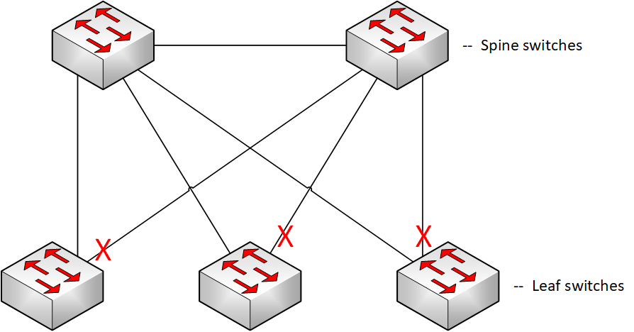
Mesh
There are several different types of mesh network topology, but this section will focus on a form of partial mesh similar to a common data center architecture: leaf-spine. While the implementation in data centers is somewhat different, there are some key points that make leaf-spine a useful topology in smaller networks.
| Mesh topology using RSTP: normal mode | Mesh topology using RSTP: self-healed after cable failure |
 |
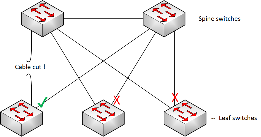 |
Figures 8 & 9 - basic operation of Spanning Tree's fault-tolerance in a leaf-spine topology
Regardless of how many leaf switches are connected to the two-switch spine, a topology change will only ever increase the hop count by 1 switch. This provides a fault-tolerant topology with a deterministic hop-count that can be used in networks of more than 9 switches. The downside of this topology is the higher port utilization required to implement it.
Combining LAGs & RSTP for bandwidth and fault tolerance
It is possible to combine the extra bandwidth of LAGs with the fault tolerance of RSTP: each uplink a LAG, and RSTP configured overall.
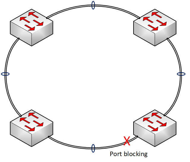
Figure 10 - LAG and RSTP used in combination
However, there is an additional condition that must be accounted for.
If just one cable of a LAG should fail, the LAG would continue to operate but with decreased bandwidth. In this situation, maintaining full bandwidth across the network would require RSTP to switch over to the blocked link, but this cannot happen until the partially-failed LAG has been fully disabled. There is a simple method to force this to occur.
Extreme networks minimum active command
The following command, when applied to a LAG on an Extreme Networks switch, will set a minimum number of links that must be active on the LAG for it to remain operational. If the number of active links falls below this number, the entire LAG is brought down.
The command is:
configure sharing <port> minimum-active <min_links_active>
If a LAG has two member ports, set min_links_active to 2 to ensure the LAG will be brought down if just one member link fails. RSTP can then unblock the fully-operational redundant LAG, restoring full bandwidth to the network's AVB devices.