Qt X Fault monitoring
Fault Monitoring can be enabled to check runs of passive emitters for shorts or open circuits. This allows the installer to check the channel impedance status of one or more runs of passive emitters. This feature only works on runs with Passive Emitters.
Detected faults will be shown in detail in the Qt X software and Web UI with a general "Output Fault" message on the front panel of all controllers in the configuration.
Emitter Run Review
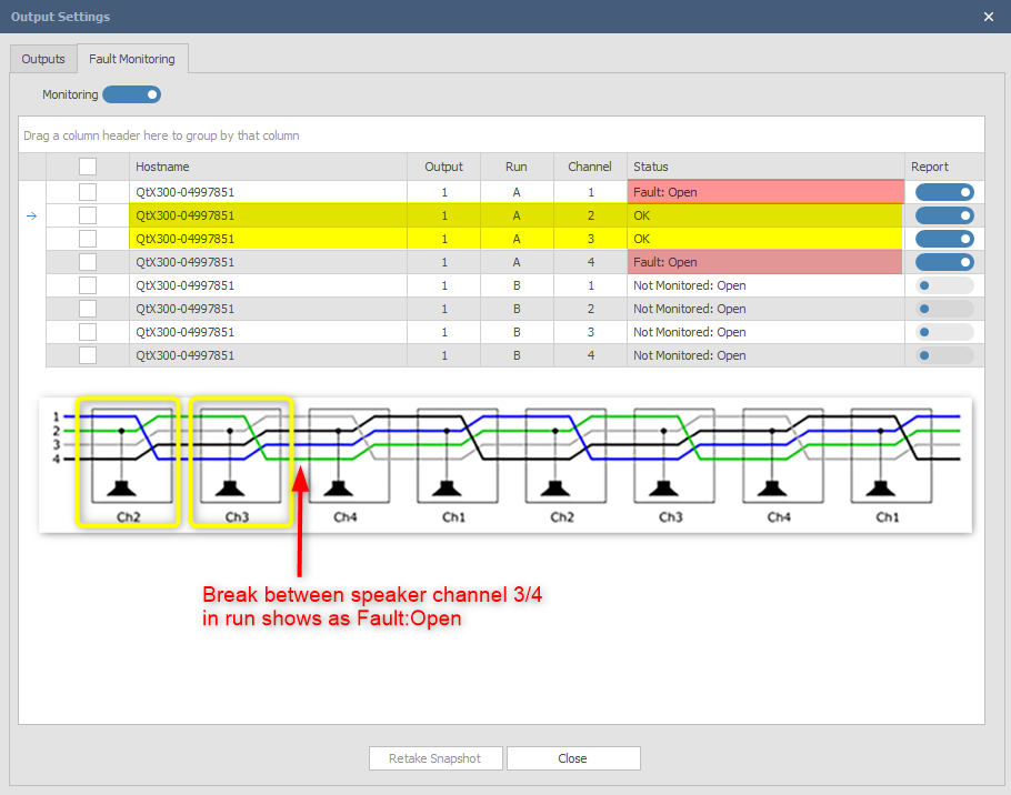
To prevent emitters from playing the same channel, they are designed to "rotate" the channels so that the next emitter in the sequence is playing a different channel from the current emitter. Each emitter loads the second channel on the cable connected to its input and changes the order of the channels going to the output connector. When emitters are correctly connected the simplified result is shown below for Run A starting with Channel 2. Run B runs from Channel 4 to 1, to 2, to 3, and then repeats.

NOTE: This feature measures the impedance on each channel, so if there is a 'Short' or an 'Open' it will show up on that channel and then all following channels on that Run.
- If all channels are showing a fault from the beginning, check the cable connections at the controller, and at the first emitter. Once you have checked the first cable, retake a snapshot to see if the first channel on that run clears.
- A reminder about the channel designations on the Runs: The first emitter in Run A will be reading from, and reporting the status of Channel 2, and the 1st emitter on Run B will be reading and reporting Channel 4's impedance status
Output X – Run A = Channels 2,3,4,1,2,3,4,1,2,3 etc.
Output X – Run B = Channels 4,1,2,3,4,1,2,3,4,1 etc.
Note: This check will not report if emitter input and outputs are swapped in the field.
Running a Snapshot
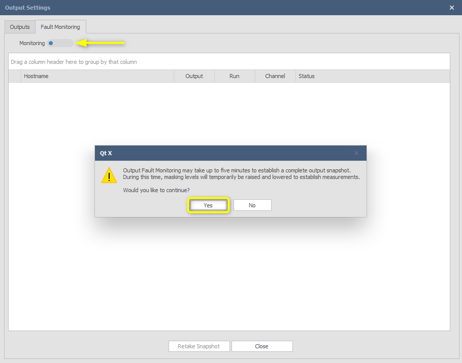
To start Fault Monitoring, select the system from the Devices and Systems view and then click on Outputs  . Open the Fault Monitoring tab and select all or specific Runs to measure by checking the boxes in the left column. Toggle the Monitoring switch on and a warning will pop up with information about masking level changes during measurement. Press 'Yes ' to continue.
Note that the process may take up to 5 minutes to establish a measurement snapshot.
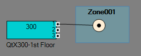
For this example, the configuration layout is utilizing a single zone using 8 emitters connected to Run A. Nothing is connected to the Run B outputs.

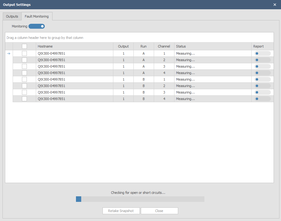
During the process, the system will measure all connected emitter runs and report back.
When the process is finished the result will be shown on screen. If no faults (shorts or opens) are discovered, the screen will show an OK status for the runs tested. This is a live test and the system will continue to monitor the impedance status of those runs until the monitoring switch is toggled off. This feature is only available in Qt X software, so once the system is checked and running correctly, it can be toggled off. The fault monitoring page will show any outputs and controllers that are defined and connected in the configuration file and associated with the controller Hostname.
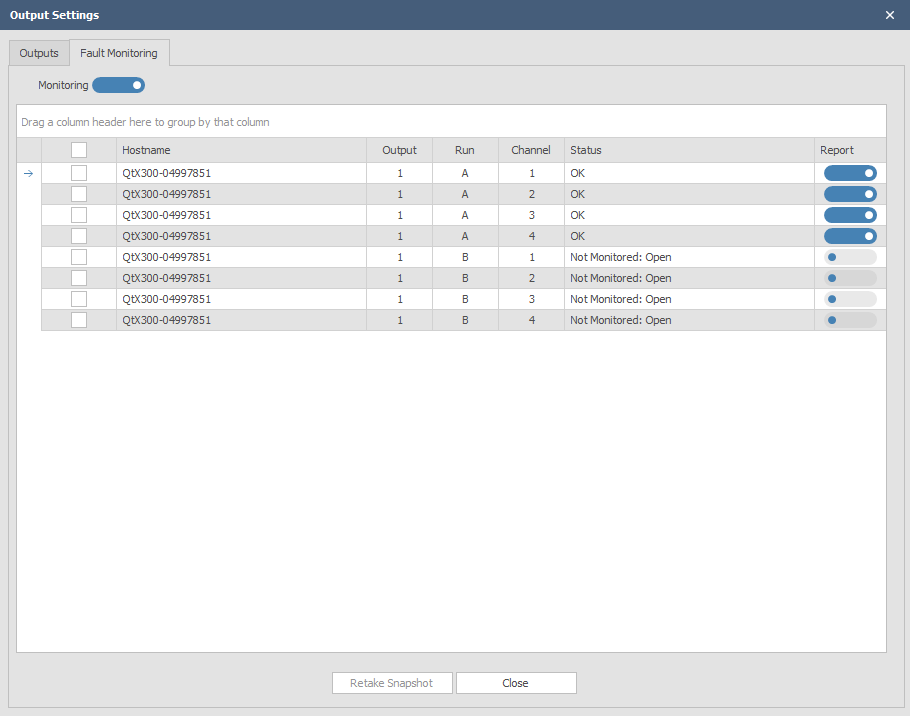
In this snapshot report, all channels on Output 1 - Run A are reporting OK with no issues detected. Any disconnected or unused runs will show as Not Monitored: Open
A new snapshot should be taken after any changes to the emitters or the wiring on the runs. Press 'Retake snapshot' to do so.
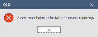
If different runs are selected or changes to the system configuration are made it is necessary to retake a snapshot to report the status correctly. A popup warning will also appear indicating a new snapshot should be taken.
Fault types
If a fault is detected in the system, it may be identified by the Run, Channel, and Status.
Fault: Open > Cable disconnected or cut in Run Fault: Short >> Short across at least one pair in Run
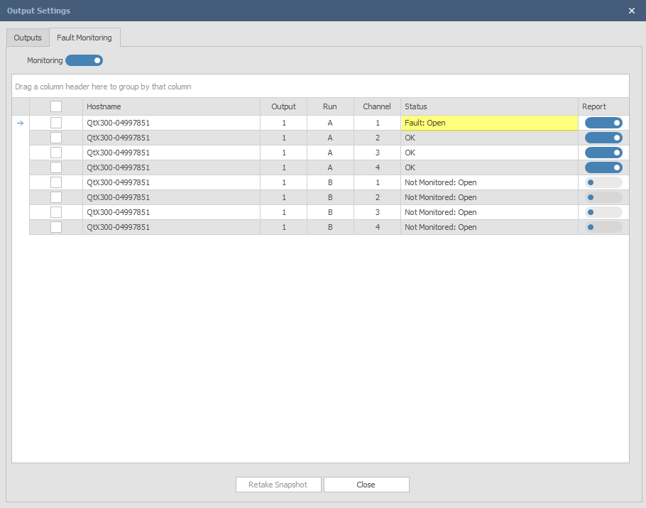
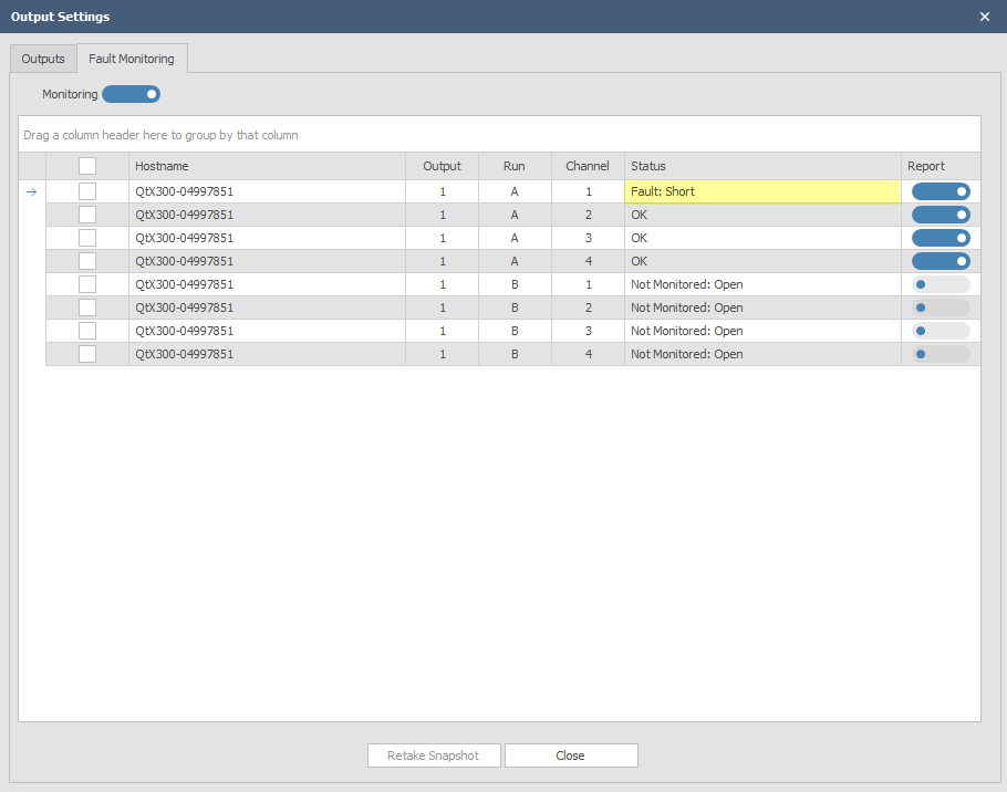
When troubleshooting runs, take into account the channel designations as shown below. More info on troubleshooting wiring issues can be found here.

Example: The location of the field issue can be better determined by viewing which channel is showing as open. If the RJ45 cable has been disconnected or cut in the field, an Open fault will be seen on the first emitter that is affected along with the next in the sequence. It is important to have the CAD floor plan layouts available to determine locations beyond the first four emitters in the chain.
