

System Design Template - Airport paging and evacuation
This system design template shows how Vocia products can be used to easily create a facility-wide paging and evacuation system for airport environments. Vocia is a highly reliable solution that provides exceptional audio quality while managing all your paging, background music, and emergency communication requirements. It's powerful, scalable, flexible, and will meet a facility’s needs well into the future. A decentralized approach, which places digital signal processing in all of the endpoints, creates a solution with no single point of failure and provides a means to expand an existing system as needs grow. Overall, airports have an extended demand on system availability and safety measures. Vocia is capable of meeting and exceeding these requirements.
System description
 The Vocia system in this example is designed to provide building-wide distribution of critical evacuation messages, regular paging, and automated announcements.
The objective is to not only provide a high level of security in case of an evacuation, but to also allow for a smart and granular zone assignments for directing announcements into individual areas including gates, lounges, shops, and common areas - or a combination of.
The total number of Worlds in this example is two, an international terminal and a domestic terminal. In each of these terminals there are 3 gates, an airline lounge, 3 shops, and the main areas, which include the walkways, food courts, and common areas. For example purposes, it will be assumed the terminals are located in separate locations and that each has their own fire panel.
If the airport was to have more than two terminals, in most cases it is advisable to expand the Vocia system by adding more Worlds. This way settings and design can be tailored specifically to suit the building layout. Separate Worlds may be necessary if the terminals are located some distance from each other.
The equipment shown in the schematic on the right and referred to for the rest of this article is for one World only, unless mentioned. This world can be duplicated for as many terminals as necessary. Both Worlds in the example contain the same settings and equipment however seeing as each terminal is unique, the configuration should also be tailored to the individual requirements.
Gates and the main area have no background music however shops and lounges do. Each shop has its own Wall Remote (WR-1) to allow background music source selection and level control. Paging has not been configured in the shop zones so shoppers are not interrupted.
The shop and lounge amplifiers have been configured with 3:1 channel redundancy. This means if a failure of an amplifier output were to occur, the amplifier will switch to this spare channel and resume driving the speakers. No additional wiring is necessary, all switching functions are handled internally and automatically within the amplifier.
Ambient Noise Compensation devices (ANC-1) have been added to the gate areas. As gates fill up with passengers the noise increases. To ensure pages are still heard over this additional noise, the ANC-1 controller will sense and increase the level of the announcement proportionately.
The paging system is also used for automatic scheduling of customer safety announcements such as 'do not leave your baggage unattended'. These messages are scheduled to play every 30 minutes but should be again customized to the building requirements.
Emergency functionality
The fire panel must be connected with Vocia's Life Safety Interface (LSI-16e) to trigger evacuation messages in case of an emergency. In order to maintain an effective and organized method of assisting staff and passengers to evacuate, the fire panel has granular access to evacuation zones. This granularity allows evacuation of individual buildings or zones in which a fire or other incident is detected, without unnecessarily alarming unaffected areas. A customized voice directive preceded by an alarm tone has been configured.
Live emergency paging can be easily added to this system by adding an Emergency Wall Station EWS-4 or EWS-10. An EWS-4 could suffice in this system as there are only 4 emergency Zones. However, if an additional emergency 'all-zone' call and/or custom emergency zone routings are required, a 10 button paging station (EWS-10) would be required.
Please note that local standards may apply to determine the design, commissioning, and operation of voice evacuation and fire alarm systems. System configuration, connection methods and sound pressure levels stated in this system design template are exemplary only and must be validated by authorities before being applied.
Paging functionality
The system allows live paging into a single or combined zones. This is possible through a DS-4 paging station located at each gate. Page codes available to these stations are configured to make announcements to the local gate, all-areas, and the airline lounge.
Equipment list
Per World, the following items have been used
- 2x VA-4030e Amplifiers
- 1x VA-8600 Amplifier
- 1x VI-6 Mic/Line Audio Input
- 1x LSI-16e Life Safety Interface (includes IM-16 module)
- 1x CI-1 Control Interface
- 1x MS-1e Message Processor
- 3x DS-4 Desk Paging Station
- 3x ANC-1 Ambient Noise Compensation Controller
- 3x WR-1 Wall Remotes
- Biamp Desono speaker - qty as required
Note that other non-Biamp equipment is required, such as fire alarm panel equipment and Ethernet switches.
Vocia configuration file
A complete Vocia configuration file is available for download here:
This file contains most of the necessary settings to get the system into an operational state, although customization to the individual facility is required. Audio files will need to be tailored to the building so they have not been included. The Vocia software must be installed to open and review the configuration file. In order to provide a better understanding on the most essential settings inside the software, the Zones and Page Code assignment dialogs can be previewed below.
| Zones Configuration | Pages Codes | Emergency Messages | Emergency Zones |
 |
 |
 |
 |
| Life Safety Interface | Amplifier Zone Assignment Regular paging: Gates 1 - 3 & main areas Emergency paging: Emergency Zone South |
Paging Station | Scheduler |
 |
 |
 |
 |
- Zone assignment - 3 gates, 3 shops, airline lounge, and main areas.
- Four emergency messages - Each message plays an audio file directing people to the designated meeting point for that zone. These emergency messages comprise of 2 elements: an Alarm tone, and an audio file defining the location of the meeting point and directions to get there. This message will repeat as long as the system is in Emergency operation or until silenced at the fire panel.
- All amplifiers use a 70V speaker line and are capable of being used for emergency voice directives.
- A VA-8600 amplifier powers the speakers used for the main areas and gates. This is a larger amp due to the additional power and number of outputs required to cover the zones.
- The LSI-16e is used to switch the system from non-emergency to emergency mode in the event of a fire or other critical event.
- The message processor (MS-1e) is used for hosting recorded messages, scheduling of announcements, email reporting of system health and also communicating with other MS-1s on the network.
- A report for Critical/Major/Minor alarms and Emergency activity has been configured to send weekly. All emergency activity has been configured to send immediately.
External connections to the system
Fire panel connection to the LSI-16e
The functionality of the LSI-16e has been tailored to the specific requirements in the EN 54-16 European life safety standard. However, the LSI-16e and CI-1 are still applicable in installations that require highly reliable and fault-tolerant systems with voice evacuation functionality, even if there is no need to meet EN 54-16 standards. Some notifications are specific to EN 54-16, for example, General Fault, General Alarm, Protection Fault, etc and may not be applicable for your jurisdiction. More information on Alarms and Faults can be found here. In this application using the CI-1 facilitates connectivity to the Fire/Evacuation Detection System (CIE) allowing bi-directional control and monitoring.
Setup requirements:
- Links between the LSI-16e Life Safety Interface and CI-1 Control Interface is achieved via the supplied jumpers. A detailed setup guide can be found here
- A 24v external power supply to the CI-1 is required.
- System Fault link between LSI-16e and Fire Panel, allows fire panel to alert when the Vocia Evacuation System has a System Fault and requires attention
- Voice Alarm Active link from VA terminal on the CI-1 to CIE - Signals the CIE that Vocia has an active alarm
- General Fault link from the GF terminal on the CI-1 to CIE - Signals the CIE when there's a fault in the Vocia System
Optional:
- Alarm Silence link from CIE to SI terminal on the CI-1 - Silences the alarm in the Vocia System
Required physical connections general purpose inputs: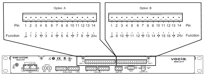
- Inputs are configured as "High-Range monitored". This means an open circuit condition from the source device to the LSI-16e will be reported before an emergency happens and the system is found to not be operational
- Loss of individual connections will be indicated as a General Fault (GF)
- LSI-16e Inputs 1 - 4 provide a mute state for the 4 emergency Zones. During this time the system is still in emergency operation, however tones and messages are silenced.
- LSI-16e IM-16 Inputs 1 - 4 provide Alarm activation of emergency messages. These put Voica into emergency mode and commences voice evacuation.
- LSI-16e IM-16 Inputs 6 - 9 will take individual Zones out of emergency mode operation
- LSI-16e IM-16 Input 11 will takes all zones out of emergency operation which will resume regular paging and system operations.
Please refer to the picture on the right showing the IM-16 inputs on the LSI-16e expanded and/or review the full LSI-16e connection documentation here
Speaker lines
- Speaker circuits are being installed as 70V constant voltage speaker lines in this example however 25V, 70V or 100V options are available for the VA-4030e, and for the VA-8600 - 4, 6 or 8 ohms, 70V or 100V options are available.
- The total power of parallel-connected speakers should not exceed 30W per channel for the VA-4030e lounge and shop amplifiers or 200W for the gates and 600W x 2 for servicing the main areas. The desired wattage on the VA-8600 is definable on a per channel basis up to 600W per channel, up to a maximum of 2400W per chassis.
- Select speaker transformer taps individually to allow for the messaging to be at least 10dB SPL above the A-weighted noise floor in each area. Note that in quiet areas, like the shop and lounge area, the speaker may provide enough SPL even at the lowest tapping.
Control network
- The control network port (LAN 1) of the MS-1e's can be connected to the building-wide network (optional).
- A free static IP address for the MS-1e should be determined with the IT manager
Networking details
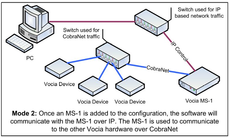 Vocia supports two modes of network communication depending on whether the configuration contains an MS-1e Message Processor or not. If it does, the computer running the Vocia software is required to be connected to the IP network for control, configuration updates and real-time feedback from devices. For systems that do not contain an MS-1e, the computer should be connected to the CobraNet network.
This particular configuration uses an MS-1e, therefore its LAN-1 port, as well as the control computer, should be connected to the IP network. LAN2 should be connected to the CobraNet network. The MS-1e will then act as the bridging device from the IP network to the CobraNet network where all other Vocia devices should reside.
Both MS-1e's need to reside on the same subnet where each IP address is required to be unique. The factory default IP address for the MS-1e is 192.168.1.101 which is what has been pre-configured for use in the domestic terminal. For the MS-1e servicing the international terminal, its address has been set to 192.168.1.102. Should any problems occur to connect to the system, connect the control computer to the CobraNet network and use the MS-1e device maintenance tool from the Vocia Software.
The CobraNet network should always be isolated, or placed in its own VLAN away from other network traffic. This is due to audio transmissions requiring high bandwidth for uninterrupted communications.
Setup Requirements
The following devices will require 802.3af (Class 3) power from a PoE capable switch or a suitable PoE injector:
- 1x LSI-16e Life Safety Interface - 2x ports of PoE required
- 3x DS-4 Desk Paging Station
- 3x ANC-1 Ambient Noise Compensation
- 1x VI-6 Background Music Input device
- 3x WR-1 Wall Remotes
System setup
All Vocia devices are set, by default, to unity gain. This allows the system to start working, once the file is loaded, with minimal adjustments.
- Select output voltage on the amplifiers to 70V or 100V as needed. The rotary encoders on the rear of the VA-4030e also need to match the setting in the software.
- Adjust the amplifier output level as needed for each zone. Start low and increase until a comfortable level is achieved.
- Check and confirm adequate DS-4 microphone input level from the Audio & Live Control tab found under the respective units properties.
- Verify there are no Alarms or Faults active in the LSI-16e. If present, verify wiring and terminations.
- Test the Emergency Evacuation Systems with each of the triggers for proper functionality and validation.