Designing mix-minus systems
Mix-minus system design is as much art as it is science. In this article, we’ll show you four best practices that will help you master the science of mix-minus. You’ll learn the right formula for determining gain settings and the physics behind it. This article should provide a good resource in helping make your next design a success. There are also links at the end of this article that will take you to our mix-minus System Design Templates to help get you started.
A closer look at mix-minus applications
Mix-minus configuration is used to create unique audio feeds to any loudspeaker in the same acoustical space. According to the Handbook for Sound Engineers, “A mix minus output signal contains all input channels except for one or more, i.e. the complete mix of all inputs ‘minus’ one (or more) undesired inputs.”
As conferences become larger and participants are more physically distant, the need for mix-minus increases. Understanding mix-minus design will help you take on these challenges:
- Systems are larger, spaces are bigger, but participant speech still needs to be intelligible.
- Current DSP products combine auto-mixing, attenuation, and routing in a single “box.” Mastering mix-minus will allow you to take advantage of the efficiencies and convenience of these DSP solutions.
- Large spaces create special issues—both architectural and acoustical.
The primary reason to design a mix-minus system is to prevent feedback in conferencing or sound reinforcement applications. In a sound reinforcement scenario, the mix of audio playing from the loudspeaker closest to the presenter should not include his own speech. Effective mix-minus configuration increases the mic-to-loudspeaker distance, which minimizes the possibility of feedback. Loudspeakers are always on but do not carry signal from every source in the system – only the ones that would be difficult to hear otherwise.
Six zone mix-minus configuration example:
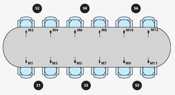
Let’s consider how this application can be improved through mix-minus design: A long boardroom table is depicted in the figure above.
The boardroom has six zones, each containing a microphone and a loudspeaker. The loudspeaker in Zone 1 is 3' away from the mic in Zone 1. As you move further down the table, the distance between the Zone 1 mic and the loudspeakers in the adjacent zones increases. If all zone loudspeakers receive the same mix of all mic signals in the room, it is very likely that you’ll create feedback with the microphone and loudspeaker in Zone 1 because they are in close proximity. Zone 1receives a mix of all microphones minus the Zone 1 mic. This enables all participants to hear each other clearly without feedback.
Inverse square law
The inverse square law is defined as “any physical law stating that a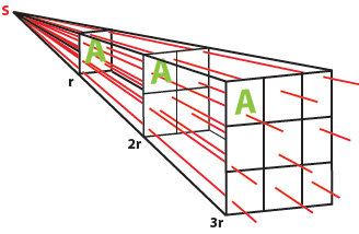 specified physical quantity or strength is inversely proportional to the square of the distance from the source of that physical quantity.” In non-physics-major terms, it means the farther away you get from sound, the lower in volume it seems to be. This happens because distance affects the sound pressure level (SPL). In fact, the SPL decreases by half for every doubling of distance.
Practically speaking, the inverse square law means that without sound reinforcement, the further your seat is from the person speaking, the harder it will be to hear. And there is another problem — the bass loss problem. Not only will the sound be perceived as less loud, it will also be deficient in the bass frequencies. Without compensating for bass loss, the unlucky participants in the back row will not hear audio that sounds natural.
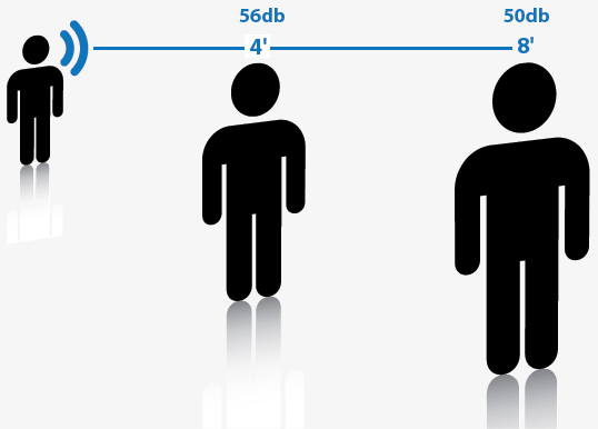
For example, if you move from a distance of 4’ away from the person speaking to 8’ away, the voice level will decrease by 6dB. The reverse is also true. If you move from 8’ to 4’, the voice level will increase by 6dB.
To offset the effects of the inverse square law, we must determine the amount of sound reinforcement required.
The mathematical equation for calculating this is:
Snew=Sref + (20 * Log10 (Dref/Dnew)
Where:
Dref = Reference Distance
Dnew = New Distance
Sref = Reference Sound Level
Snew = New Sound Level
There are a number of mathematical formulas to help you uncover Potential Acoustic Gain, critical distance, how much gain is needed, and how much the system can produce. But if you’re not a math guru—and few of us are—you can fortunately arrive at the same answers with a sound level meter.
Four Best Practices for Mix-Minus Success
While there are many steps to configuring mix-minus, particularly the more complex the installation, mastering these four techniques will help you avoid the most common mix-minus issues.
Set proper gain structure
Improperly configured gain structure is the number one killer of mix-minus and acoustic echo cancellation (AEC). Your goal in creating a gain structure is to get equal, balanced signals into the microphones and then out of the system. The steps to gain structure include:
- Establish ample signal strength at the first part of the signal chain (microphone). Creating consistency among all mics is the primary goal.
- Adjust input gain and check peak levels. Add just enough gain for enhanced intelligibility and comfortable conversation.
- Monitor the signal chain with meters.
- Maintain good signal strength through audio path.
- Keep the signal strong, attenuate at the end (frequently at the power amplifier).
The starting point is to determine the level of a typical talker (person speaking) in the room and set up your mic for that level. The average level for a talker in a quiet room is 65dB when measured from the talker to the microphone, at a distance of 2.5 feet. Configure the input gain for every mic such that the input level of each while it is being spoken into at a typical volume and from a typical distance is as similar as possible. In many cases, this will require different input gain settings for different mics in the room.
For this reason, it is critical to test every mic in the system. When you design a mix-minus system, you assume that when you speak into a mic at 70 dB, it’s going to come out the speaker at the desired level. If one of the settings along the chain is not the way you think it is, your assumption is wrong and so is your system.
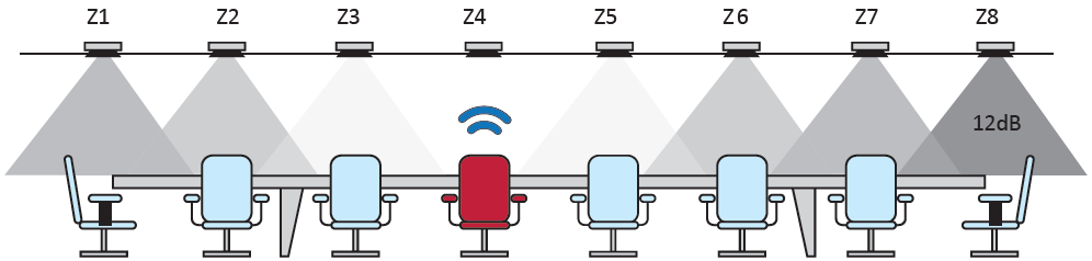
The amount of sound reinforcement required depends on the distance from the listener to the talker. In the example above, if the talker is in zone 4, zone 8 will require the most reinforcement. The 8 Zone layout above shows a typical attenuation pattern for a talker located in Zone 4. In this example, we lose 3dB from Zone 1 to Zone 2, 6dB from Zone 1 to Zone 3, and 12dB from Zone 1 to Zone 4.
Determine attenuation from zone to zone
Some systems integrators and contractors like to set up their design file prior to coming on the job site. If you know the distances between the mics, loudspeakers, and participants, you can run your mathematical equations ahead of time. This approach will get in the ballpark with your attenuation setting. However, you will still need to adjust the settings to compensate for room acoustics. Whether you decide to set up a design file beforehand or simply test from scratch is up to you. Both approaches will work.
This is where the inverse square law factors in. The normal level for someone in a quiet room is 65dB. Every doubling of distance away from that person will reduce or attenuate the sound level by 6dB. If you move from 2 feet from the talker to 16 feet away, the SPL will drop by 18dB and you’ll hear the person at about 47dB.
There are two ways to calculate this. The first way is to count how many times the distance has doubled. From 2 ft. to 4 ft. is one doubling, 4 to 8 is the second, and 8 to 16 is the third. Each doubling reduces by 6dB, so 6 x 3 = 18dB. The second way is to use the equation introduced above:
Snew=Sref + (20 * Log10 (Dref/Dnew)
Snew = 65 + (20* Log10 (2/16)). Snew = 46.94dB
To provide the same experience the person enjoyed when standing close to the talker, you will need to compensate for the attenuation. To do this, ensure that the direct level + the amplified level = the desired level. In this case, the direct level is 47dB and the desired level is 65dB. Since the direct level is so low, it only contributes negligibly to the desired level. So, you would need the speaker to produce a full 65dB level at this listening position.
Mix-minus position 0 is the position that receives full level from the noise source without reinforcement. By using a meter or math, determine how much attenuation occurs from zone to zone.
Compensate for NOM
The Number of Open Mics (NOM) is another potential pitfall for mix-minus systems. NOM is based on the fact that, for every doubling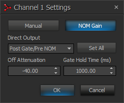
in open/live microphones (1-2-4-8), the potential for feedback increases by 3dB. NOM attenuation is a method of ensuring that the overall level (not gain) in the room is as consistent as possible.
In mix-minus systems, the best practice is to use pre-NOM attenuation outputs on the direct out because you have already determined the attenuation for your system. By default the Tesira software is set to pre-NOM attenuation on outputs.
It works by taking note of how many microphones are being used simultaneously, and reducing the overall output level such that an increase in the number of mics won’t result in an increase in level. In other words, a person talking into one mic at 70dB yields a 70dB output. Two people talking into two mics at 70dB yields a 73dB output, so NOM attenuation would attenuate by 3dB to compensate. Four people talking into four mics at 70dB yields a 76dB output, so NOM attenuation would reduce the level by 6dB to compensate.
NOM attenuation is used in auto mixers in live sound applications to help control feedback by attenuating the output every time more
microphones are added to the mix. However, in smaller, properly designed mix-minus systems, feedback is not an issue. In general,
NOM usage needs to be limited as much as possible. Set NOM limit to about 20% of the available mics.
Practice good system design by planning for the application
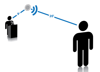
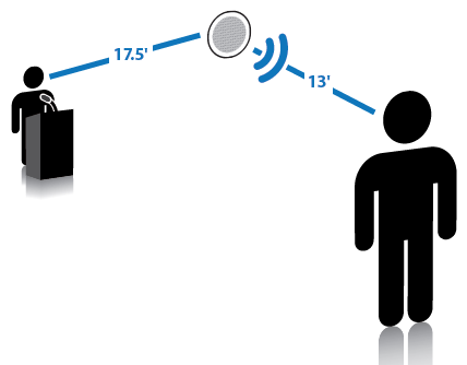
The fundamentals of good room design are critical to a successful mix-minus system. There are two areas in particular that will have a significant impact. The first is microphones and loudspeaker placement. The second is acoustic treatments. The first rule in mic application is to get the mic as close as possible to the sound source.
General rules for mic design are:
- Avoid close coupling of microphones and loudspeakers
- Increase Echo Return Loss (ERL).
- Use microphones that minimize distance to conference participants such as a gooseneck-type.
- Avoid ceiling mics because they will typically be closer to the loudspeaker than the talker.
|
Close coupling of mic and loudspeaker |
Improved mic and loudspeaker positioning |
General rules for room acoustics include:
- Rooms that already yield poor intelligibility make for terrible conferencing rooms.
- Correcting an acoustical problem is best solved using acoustical treatments.
- Surfaces such as carpets, acoustic tiles, and bookshelves are good surfaces to absorb, dampen or at least attenuate acoustic echo and increase ERL. On the other hand, highly reflective surfaces (glass, bricks) will tend to reflect most of the acoustic signal and create reverberation.
A quick word about AEC
Whenever a mix-minus design includes conferencing capabilities and AEC references it adds a level of complexity. Most importantly, you will need to synchronize the level control for sound reinforcement signals with the level control to the AEC reference. Any level changes made to the sound reinforcement feed needs to be reflected to the AEC reference. Here are common issues to watch out for:
- AEC may cause artifacts in audio signals. It is important to always choose a high-quality DSP processor and follow gain structure best practices.
- Local reinforced audio may cause false gating of microphones. The safe solution is to just turn down the volume of the reinforced audio, or reduce the maximum NOM in the auto mixer. You never want to send a microphone to its own references, but in some cases, you can send other microphones a reference. If done properly, this will result in the reinforced audio being canceled from those inputs and no longer incorrectly gating the mics.
- The mic is hearing a different set of signals from the speakers than another microphone. Multiple references may be required in larger spaces.
- Wireless microphones may roam between speaker zones. Mobile microphones generally cannot be integrated into mix-minus systems in a meaningful way. Avoid if possible.