Mix-minus conference room system
This system design template shows how Tesira products can be used in a mix-minus conference room scenario. In this design, the primary purpose is to provide the highest possible gain before feedback in a conferencing space by selectively attenuating or eliminating a microphone’s contribution to nearby loudspeaker zones. It is important to prepare for a mix-minus design by performing all the Potential Acoustic Gain / Needed Acoustic Gain (PAG/NAG) calculations before the system is installed. This template is provided to show an example approach to this design for reference. In a real world design, factors like room size, furniture, microphone type and placement, and acoustics of each space will need to be taken into consideration.
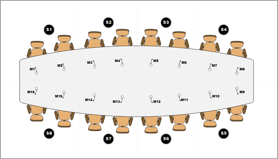
In this example, the conference room is designed to include 16 table-mounted gooseneck microphones for voice lift through 8 ceiling speaker zones for mix-minus. In addition to voice lift, these microphones will also provide audio to far-end participants utilizing VoIP and/or a USB soft codec. The conference room is outfitted with zoned ceiling speakers for speech reinforcement and conferencing along with stereo wall speakers for playback of program audio. System design makes use of Tesira PoE+ AVB amplifiers and Desono speakers to help to streamline the room installation by using standard CAT5 cabling. Bluetooth audio connectivity is also provided for conference integration or streaming to the system. The Tesira system is designed with control points to allow for integration with third-party control systems for various level, mute, and dialing functions.
Room design
Room Functionality Scope:
- 16 gooseneck table microphones at conference room table participant locations
- Connection to building VoIP phone system
- USB connection in room to local PC for soft codec integration
- Bluetooth audio connectivity
- Stereo program source audio inputs
- System control via third-party control system
- 8 zone ceiling speaker system to support mix-minus voice lift capabilities
- Stereo speakers for playback of program sources
.png?revision=1)
Equipment list
Below is the list of Biamp equipment used in this project:
- 1 - Server-IO AVB SIC-4(1), SEC-4(4), SOC-4(1), SVC-2 (1), DSP-2 (1): 16 mic/line inputs with AEC, 4 mic/line inputs,4 mic/line outputs, AVB, and VoIP
- 1 - Tesira EX-UBT AVB/USB Expander with Bluetooth® Wireless Technology, powered by PoE+ (IEEE 802.3at Class 2, 7W)
- 2 - AMP-450BP 4-CH PoE+ backpack amplifier providing 4x 50 Watts burst power with RJ45 speaker outputs designed for use with Desono C-IC6 speakers
- 1 - AMP-450P 4-CH PoE+ amplifier providing 4x 50 Watts burst power
- 16 - Desono C-IC6 Wide coverage two-way, passive coaxial design ceiling speakers (dispersion angle of 130°) optimized for voice reproduction
- 2 - Community V2-6 6-inch Compact Full-Range Two-Way Compact Point Source Loudspeakers, 100W continuous @ 8 ohms
- 1 - TesiraCONNECT TC-5 5 port AVB room expander with 120W of PoE+ budget.
Note that other non-Biamp equipment is required, including the gooseneck table microphones, control network switch, and stereo program source device.
Example files
 The example file for this system design template is set up with all the audio I/O, processing, and control points required, and is ready to load to the system and begin setting up the room gain structure. In the file, the matrix routing is already in place to support the room design requirements. Mix-minus zone output levels in matrix mixer are shown as a starting point and will need to be adjusted based each room's requirements and PAG/NAG calculations.
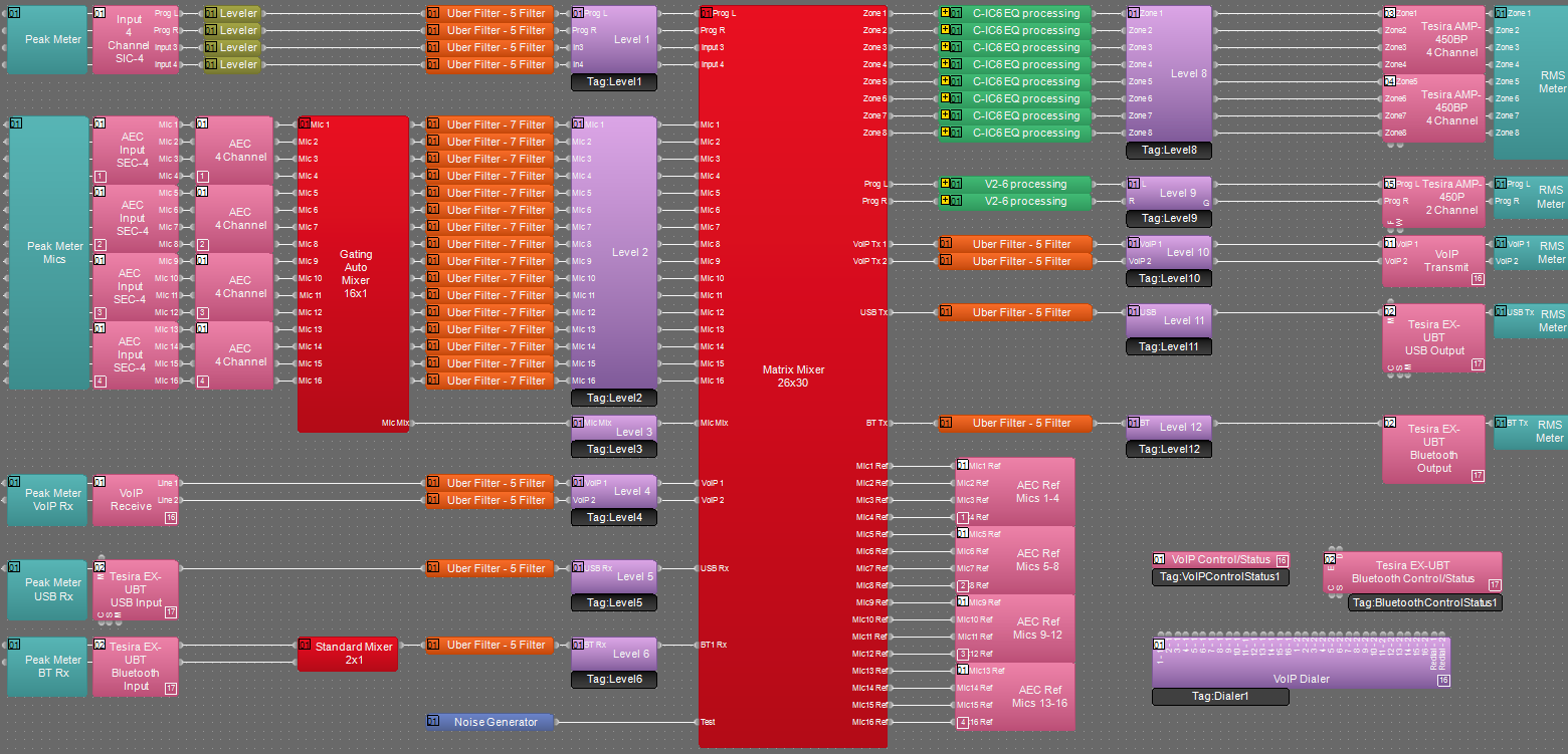
16 AEC audio input channels on the Server I/O are used for the 16 conference table microphones. The file uses a gating automixer with direct outs enabled to allow for room reinforcement outputs as well as mixed outputs for conferencing. Mixed room microphone signals are routed to the VoIP, USB, and Bluetooth outputs. There are a pair of inputs to support stereo audio feeds from the program sources. There are 8 zoned outputs to feed the distributed ceiling speakers in the room for speech reinforcement. Program sources and Bluetooth audio inputs are routed to the stereo left and right speaker outputs in the matrix. Conference signals are routed to the distributed ceiling speaker zoned outputs in the current matrix configuration.
To assist with deployment and commissioning of systems which include the Desono C-IC6, a Tesira Library File (.tlf) has been created. This includes a custom block with Biamp's recommended EQ curves to optimize the sound of the C-IC6 loudspeaker. This custom block has been included in the system design template. The Tesira Library File and can be downloaded from the link below if needed. This library file is also included in the file download package.
USB initialization in the file has been setup to support a 1x1 audio configuration with computer AEC disabled for the USB to PC connection. All AEC references have been made in the matrix mixer for proper echo cancelation of conferencing sources utilizing a per channel AEC reference topology. The file's Equipment Table is populated with proper hardware to match the layout, but will need to have serial numbers and proxy host assignments added before loading the file to system.
The .zip file below contains the example Tesira configuration files for this mix-minus conference room application along with signal flow, room layout diagrams and processing library files.
File Download: Mix-Minus Conference Room System
Networking details
The mix-minus conference room application will make use of the control and AVB network interfaces of the Server I/O hardware to achieve a fully functioning room environment. To get this design properly running on our hardware, we will need to prepare the control and AVB sides of the network. For a more detailed guide on how to implement in a larger range of network applications, it would be helpful to reference our Tesira Network Infrastructure article. In our application, we will approach the implementation as a smaller scale setup with separated control and AVB networks as shown in the room signal flow diagram. In this approach the EX-UBT, AMP-450BP, and AMP-450P expander devices will be discovered through the AVB connection rather than through the control network connection.
Setup Requirements:
- Control network connection via switch, direct connection, or building LAN.
- The TesiraCONNECT TC-5 device provides 5 ports of AVB and 120W of PoE+ budget. This provides full PoE+ power on 4 ports.
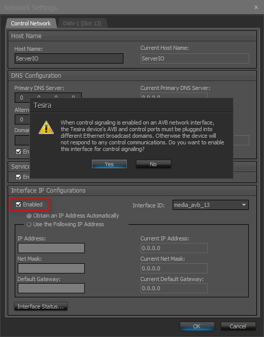
- Separated Networks mode enabled. This is done through the Network Settings button in the Device Maintenance window. The Network Settings dialog will display the settings for the Control NIC by default. In the drop down list in the Interface IP Configurations section, select the AVB media NIC. Check the Enable box to activate the IP configuration for the AVB interface. This will enable the device's AVB network interface to discover Tesira's expander and control devices. Verify that the AVB and Control networks are logically separated, and the IP addresses assigned to them must be in non-overlapping subnets. See the Essential rules section for more information on requirements when using separated networks mode.
- Units running FW 3.8 or later can also be setup using the Single Network Connection if desired.
- Note that the EX-UBT, AMP-450BP, and AMP-450P use Layer 2 AVB for audio and control data, IP address setup is not required.
After these control and AVB network setup steps are complete, you will now be ready to send your compiled system configuration to the hardware.
Note: This application example can also be setup with a converged network if required. Up to (4) TesiraCONNECT devices may be daisy chained to expand the total AVB/control network port count of the system.
Audio setup
- Follow Gain Structure best practices to set input and output levels of microphones and sources. Input and output gain levels have been left at default settings for integration flexibility of the file. Input and Output metering has been added to assist with setting gain structure within the file. Additional meters can be added to the file as required to allow for additional detail at point along the signal path.
- Tesira AMP-450BP amplifiers in the file have been setup to deliver 4 channels of audio output at 3W per channel with a speaker count of 2 for each zone. Adjustments to this setup may be made as needed to match room requirements.
- Tesira AMP-450P amplifers in the file have been setup to deliver 2 channels of audio output at 7W per channel with a load impedance of 8 ohms.
- Ensure that the proper VoIP setup is done and the system is ready to make and receive calls.
- Connect USB to PC for soft codec integration if required. Reference the Using the Tesira EX-UBT article for more details on working with the EX-UBT.
- Select constant voltage(CV) if required and bridging on amplifier channels as needed to support room speaker topology.
- Reference AEC best practices documentation and begin to do some test calls with the system. ERL values between 0dB and +15dB are optimal.
- Level and mute controls have been added to the file pre and post matrix mixer. These are added for flexibility to meet the design criteria and tastes of the client or integrator. These level controls have maximum and minimum ranges set in place, but can be adjusted to fit the needs of the space and design.
- Uber Filters have been added to all signal paths to allow for any additional equalization as needed to sources. It is recommended to use the advanced filters section of the AEC channel processing block for for any high pass filtering needed on conference table microphone inputs. Additional filtering or dynamics blocks may be added or changed as needed to achieve the desired results in the file.
- Follow proper room equalization procedures for speaker zones to optimize gain before feedback performance of the system. Parametric equalizers are added on all zoned speaker outputs to assist with room tuning and optimization.
- Matrix mixer crosspoint assignment and starting zone levels have been set, but will need to be adjusted per room. Values are set in place as a starting point of reference. Utilize calculations based on the room size and inverse square law to determine the amount of attenuation needed from zone to zone.
- Changes to matrix mixer can be made as needed to allow for appropriate sources to feed the stereo and mix-minus speaker zones to fit the design application.
- It is recommended that level controls for the conference microphone inputs and zoned speaker outputs have max and minimum ranges limited help with system stability after room is commissioned.
VoIP setup
If a VoIP phone line is to be used, it must be correctly configured to register with the in-house VoIP phone system. Biamp VoIP interfaces have been tested and/or certified to work with the VoIP telephony systems listed here. Biamp VoIP interfaces may also be able to work with other SIP-based VoIP systems, but they haven't been tested or certified with those systems.
When integrating Tesira with one of the tested/certified VoIP systems, it is best to follow the detailed instructions in the appropriate article to ensure a successful deployment. Detailed instructions can be found in the following articles:
- Microsoft Lync / Skype For Business
- Cisco CallManager
- ShoreTel
- Mitel 3300 ICP configuration for a Tesira SVC-2 or TesiraFORTÉ VI
- Avaya Session Manager
- Avaya SES
- Avaya IP Office
- Avaya Communication Server
The basic steps to configure the VoIP interface start with opening the VoIP Control/Status block configuration dialog to access VoIP settings:
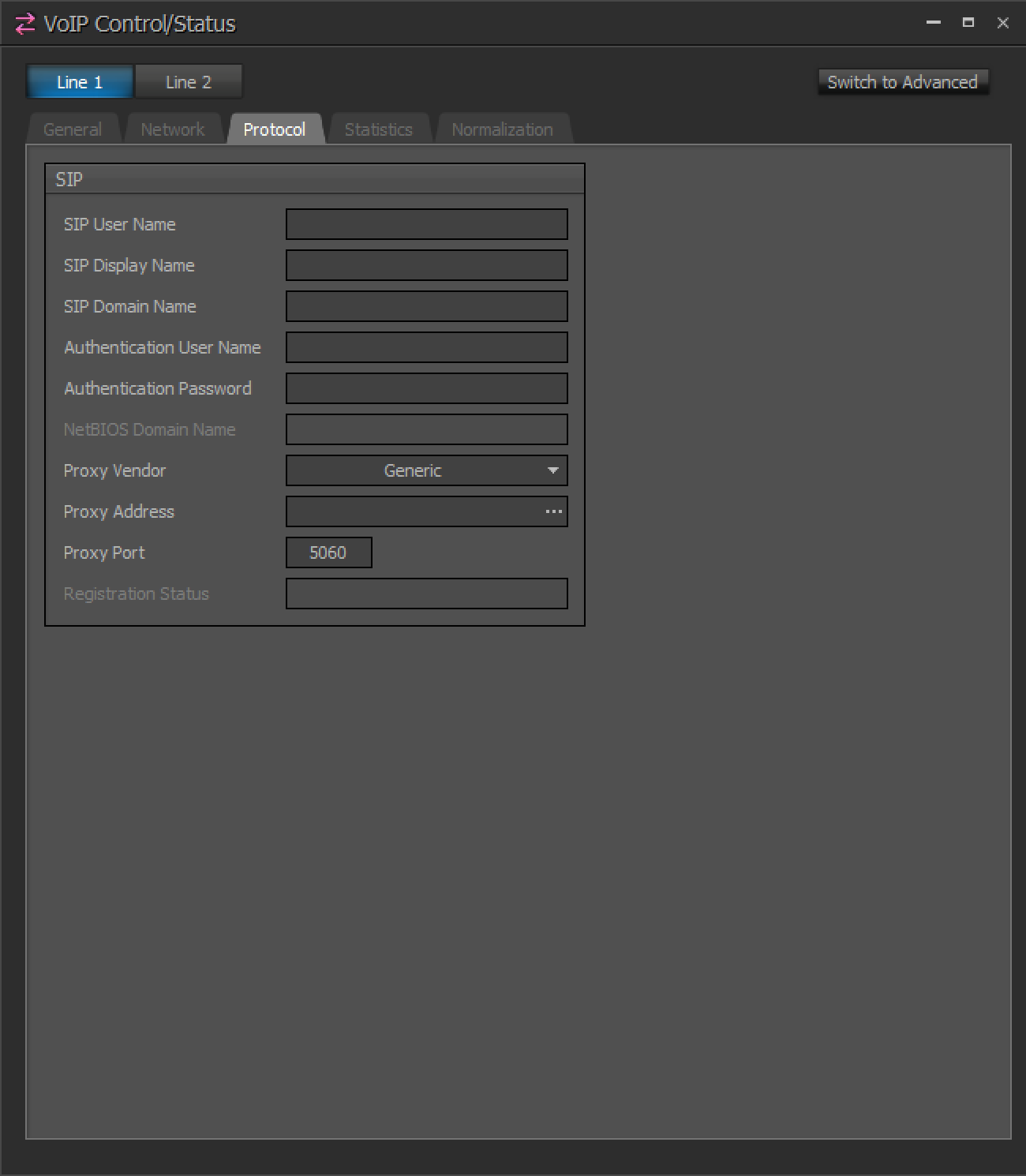
Click to see configuration dialog
Much of the above information must be obtained from the customer's IT or VoIP team. The following document was designed to facilitate the process of obtaining this information. Provide this documentation to the IT/VoIP team and ask them to fill it out:
VoIP Checklist Form
USB Integration
The EX-UBT is a compact remote expander that uses the AVB networking protocol to extend USB and/or Bluetooth sources back to a rack-mounted Tesira server-class device. A standard USB cable connects the host computer to the EX-UBT. CAT5e cabling or better is required for the network connection, with a maximum distance of up to 100 meters (328 ft) allowed to the equipment rack. The EX-UBT is an IEEE 802.3at Class 2 device requiring 7 watts of power from a PoE-capable switch or mid-span injector. Please reference our Using the Tesira EX-UBT article for further details.
Control integration
Control System Integration: The example Tesira configuration file for this application file has been setup to allow third-party control systems to easily control the Tesira system. There are control points for Dialing, Level control, and Mute already in place to allow for you to use as it as-is, or add to as needed to suit the needs of the client. Level controls have top and bottom limits in place that can be changed as needed for the design needs. It is recommended to limit the amount of user facing controls for the microphones in the voice lift portion to maintain proper gain structure in the system after the commissioning has been completed. Control points within the file have been noted with an additional text box showing their default instance ID tag. These tags can be changed as needed to suit the programmer workflow or standardization.