Microsoft Teams Large Meeting Room - TesiraFORTE and Sennheiser TCC2
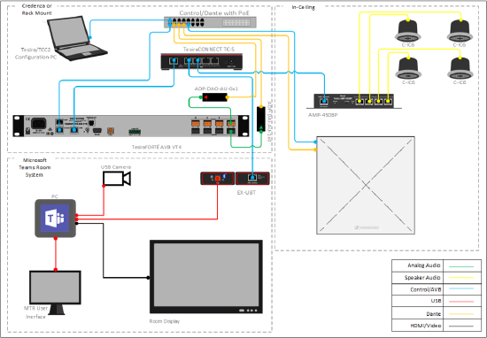
This system design template shows how Biamp Tesira and Microsoft Teams Room systems can be integrated with the Sennheiser TeamConnect Ceiling 2 mic array to support a large meeting room.
In this example a large meeting room is defined as a meeting space about 15' x 28' (4.5m x 8.5m). This system supports Microsoft Teams meetings, with all control originating from the Microsoft Teams Room user interface. The TesiraFORTÉ and EX-UBT communicate with Microsoft Teams to sync mute state from the user interface and allows this status to be reflected on the TeamConnect Ceiling 2 LED indicators. A PoE+ amplifier mounts directly to the Desono ceiling speakers, which are located at suitable positions to evenly cover the meeting room with the far-end voice and USB audio. The TeamConnect requires Dante for routing signals to and from the ceiling microphone. Single channel Dante to analog input and output convertors are used to facilitate the connection to a physical input and output on the TesiraFORTÉ AVB VT4.
Room design
- Microsoft Teams Room System
- Ceiling Tile Style Dynamic Beamforming Microphone Array
- HID Communication to support mute sync between microphone and MTR System
- Dante Audio Network for routing of microphone signal to Dante I/O adapters
- LoZ ceiling speakers for playback of voice signals from MTR far end
Equipment list
Below is the list of Biamp equipment used in this system configuration:
- 1 - TesiraFORTÉ AVB VT4 Audio DSP
- 1 - Tesira EX-UBT USB connection to Microsoft Teams Room System
- 1 - Tesira AMP-450BP 4 channel PoE+ amplifier
- 4 - Desono C-IC6 Wide coverage ceiling speaker (dispersion angle of 130°) optimized for voice reproduction
- 1 – TesiraCONNECT TC-5 5 port AVB expansion box
Other system hardware required:
- 1 - Microsoft Certified Teams Room System
- 1 – Sennheiser TeamConnect Ceiling 2 Ceiling Mic Array
- 1 - Dante AVIO Analog Input 1ch (ADP-DAI-AU-1X0)
- 1 - Dante AVIO Analog Output 1ch (ADP-DAO-AU-0X1)
- 1 - Network switch for Tesira Control and Dante communications
- 1 - Computer running Tesira Software, Control Cockpit, and Dante Controller *
System configuration
The example file for this system design template is set up with all the audio I/O, processing, and control points required. The file's Equipment Table is populated with the proper hardware to match the layout, but will need to have serial numbers and proxy host assignments added before loading the file to system.
In the file, the matrix routing is already in place to support the room design requirements. A single AEC input channel on the TesiraFORTÉ AVB VT4 will support the connection to the Sennheiser TCC2 via the Dante to analog convertor. A single analog output channel will be used to route a reference signal back to the Sennheiser TCC via the analog to Dante convertor.
To support the conferencing needs of the space, the microphone signals are routed to the USB output. All AEC references have been made in the matrix mixer for proper echo cancelation of the far end audio.
To assist with deployment and commissioning of systems which include the Desono C-IC6, a Tesira Library File (.tlf) has been created. This includes a custom block with Biamp's recommended EQ curves to optimize the sound of the C-IC6 loudspeaker. This custom block has been included in this system design template file. These blocks can also be found in the Processing Library in Tesira software.
The .zip file below contains the example Tesira configuration file for this conference room application.
TCC2 MTR Large Meeting Room.zip
Setting the audio device from the Microsoft Teams Room System
Setup and deployment of specific Microsoft Teams Rooms hardware may vary, please see manufacturer documentation for proper operation. Once the configuration file has been loaded to the system, the EX-UBT will be available as an audio peripheral device from the Microsoft Teams Room System user interface. To select the EX-UBT, navigate to the Settings menu on the Microsoft Teams Room user interface.
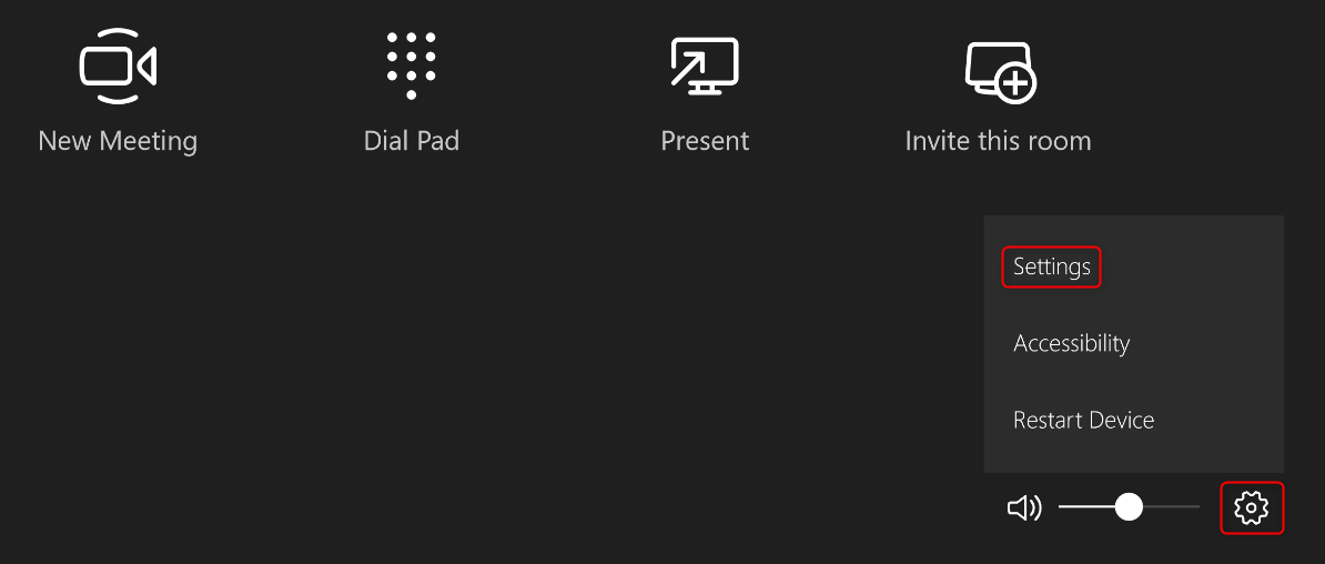
From the Features menu, use the dropdowns to select the EX-UBT.

HID communication logic
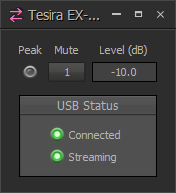
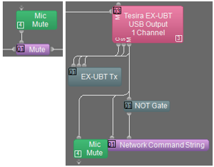
The EX-UBT synchronizes privacy mute state and volume control when connected to the Microsoft Teams Room System. This is achieved through Human Interface Device (HID) communication. Within the running Tesira configuration, room level control from the Teams Room System user interface will sync with the level control in the EX-UBT USB Input block, while privacy mute from the Teams Room System user interface will sync with the mute control in the EX-UBT USB Output block.
By default, the Microsoft Teams Room System volume control will set to 50 when a meeting is started. This level will be reflected in the EX-UBT USB Input block as shown below.

The Sennheiser TCC2 can be controlled by a 3rd party device over UDP port 45. This is accomplished in Tesira by using a Network Command String block and requires that the Tesira control port be connected to the same network as the TCC2 PoE/Ctrl port. The IP address assigned to the TCC2 PoE/Ctrl port is entered in the Server Address field.
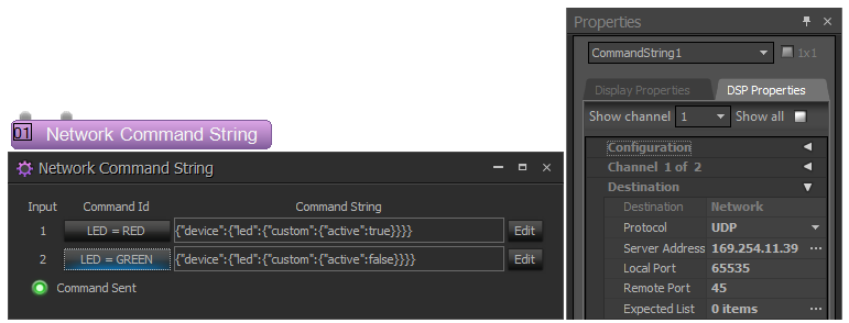
LED = RED = {"device":{"led":{"custom":{"active":true}}}}
LED = GREEN = {"device":{"led":{"custom":{"active":false}}}}
HID mute sync feedback from the Teams Room System is used to set the LED color on the TCC2, Red for privacy “mute on” and Green for privacy “mute off”. This also triggers a Mute block to mute and unmute the audio being sent to the far end participants.
When configuring the TCC2 from Control Cockpit, be sure to set the Custom Color to Red and leave the mic unmuted. Privacy mute will be handled in Tesira, post AEC processing.
TeamConnect Ceiling 2 setup and configuration
The TCC2 is a ceiling-mounted dynamic beamforming microphone. It supports both Dante (input/output) and auxiliary balanced analog (output) connections for audio transport. A PoE/Control connection and the Sennheiser ControlCockpit software is required to begin setup.
With the network cable attached to the TCC2 (“Ethernet PoE/Ctrl”-Socket) the browser-based ControlCockpit-Interface should detect and identify the TCC2-unit as shown below.

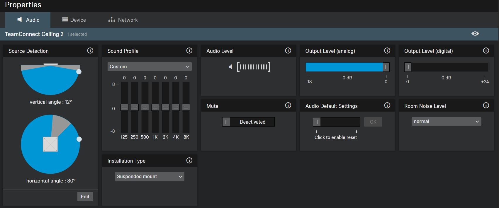
Clicking on the unit to be configured from the device list opens the settings view where system and audio parameters can be examined and edited.
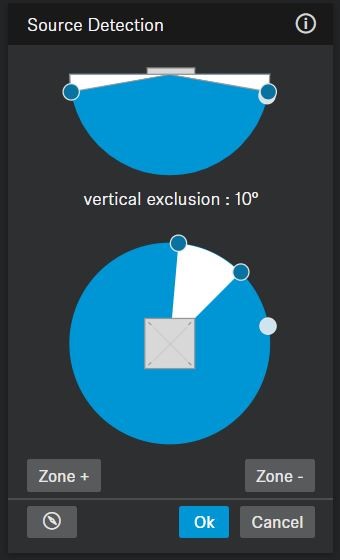
In the leftmost section of the “Audio” pane the current focus of the TCC2’s automatic beam-steering can be tracked in real-time. Via the “Edit” button the user can manually declare vertical and horizontal exclusion zones (marked grey) which will prevent the source detection from being deterred by noise sources at known locations (e.g. ceiling mounted AC-vents, projector fans).
More information can be found in the online user guide.
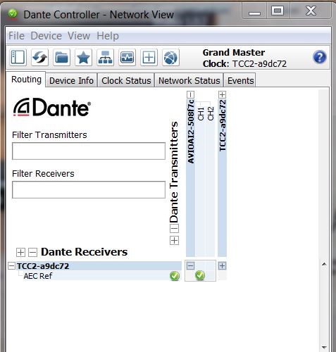
In order to improve the AEC-performance of the overall conference setup it is advisable to provide the AEC-reference signal (i.e. as being played back by the near-end loudspeakers) to the TCC2’s reference-input-channel (1st Dante input-channel), so the beam-steering can be stabilized during far end speech.
Use the Dante-Controller-Software on a computer attached to the Dante-network to adjust the routing between the respective Dante-endpoints.
.
Leveling of the AEC-reference:
The far-end signal (receive signal from the far end talker) needs to be routed from the DSP to the TCC 2 AEC Ref input via Dante. This AEC reference signal is used inside the TCC 2 to steer the beam into a static status (at 0° horizontally and 90° vertically) at any time when the far-end talker is active. The static status is enabled when the level of the AEC reference signal exceeds a certain threshold. In order to ensure appropriate functionality of this feature, it is crucial to adjust the level of the AEC reference signal. Optimally, the level of the AEC reference signal should be adjusted in such a way that the static status is not active when the far end talker is not active.
Proposed procedure to find the right level for the AEC ref signal:
Setup a test-call where the far-end talker is unmuted but remains quiet. Set the output level for the AEC ref-signal inside the control software for the AEC to minimum. In this way the position of the near-end talker should be tracked properly, never reaching the static status. The static status is indicated in Sennheiser ControlCockpit by a direction of 0° horizontally and 90° vertically. When the output level of the AEC reference signal is increased steadily, at a certain point the static status becomes active and the displayed position in Sennheiser ControlCockpit is stuck to 0° azimuth and 90° elevation. Find the level where the static status is starting to be active with a quiet far end. When this threshold is found, reduce the output level of the AEC reference signal by 10-15 dB.
Networking details
This system deployment makes use of PoE+ powered endpoints. The TesiraCONNECT provides all necessary resources to support these communications.
Setup Requirements
- The TesiraCONNECT TC-5 requires no configuration to support Tesira device communications and will provide all necessary power to PoE powered devices.
- The TesiraFORTE AVB VT4 should be configured for Separated AVB and Control Networks as outlined in this article.
- Control/Dante network switch
- Optional: PoE capable switch to provide power for the Sennheiser TCC2
- Alternate: 802.3af (Class 3) PoE injector for powering the TCC2 (if Control switch does not provide PoE power).
- Tesira Control Port and the TCC2 PoE/Ctrl port will need to be configured with addresses in the same subnet for LED mute sync control to function.
- Note that the EX-UBT, and the AMP-450BP use Layer 2 AVB for audio and control data, IP address setup is not required.
Microphone and speaker placement
Microphone placement
The laws of physics can't be ignored when deciding on the right placement of a microphone. A good signal-to-noise ratio is key in every part of the audio signal chain and for a typical microphone pickup scenario, this translates to avoiding large distances between the mic and the talker.
- Keep the distance to the talker as short as possible.
- Keep the distance to the ceiling speakers as high as possible.
- Stay away from noise sources like projector fans and air vents.
Speaker placement
Placing speakers in a room can be as equally critical as finding the right spot for a microphone. An ideal positioning of multiple ceiling speakers will achieve an even SPL coverage and a good speech intelligibility across the entire room.
Desono Speaker Calculator
The Desono speaker calcualtor can aid in determining the correct number and proper location in which the ceiling speakers should be located.

