Multi-PC/camera conferencing - Medium 12-seat room
The expectations of conference technology continue to change over time. With the wider adoption of working from home, in group meetings we have become accustomed to viewing each other face to face in camera shots that are framed to the individual. This comes in contrast to the previous experience where a group meeting done in person may have utilized a camera shot which framed up the entire group from one end of the room.
This article provides a solution for a group meeting of local participants to each appear with their own personal camera shot as provided by their laptop while seated at the table with the rest of the local group. Those watching on the far end will have a hard time distinguishing between those who are true remote participants and those individuals in the group who are in the local room. Each person brings to the local meeting their laptop with UC client software. The UC software of choice is not critical (commonly Microsoft Teams, Zoom or Google Meet) but all participants must be on the same UC platform and in the same UC meeting. Each participant’s laptop is to be equipped with a camera that will be used during the call. All audio functions for the meeting are provided by the room’s Tesira system using a USB connection to each local laptop for connectivity.
In a bridged conference call, whether it be based on a phone or UC client endpoints, utilizes the mix-minus strategy for audio to be sent to everyone that needs it without individuals hearing themselves forming a loop. The proper management of the mix-minus audio that each UC client uses is essential for this solution’s success.
During the meeting, each local UC client plays active role. The programming within the Tesira keeps each UC client in line. For a seating position to be considered for participation in the meeting, the USB cable must be connected and have active audio. Upon connection, the Tesira system will set the UC client’s speaker volume to full and lock it. The speaker will also be unmuted if it is. During the call, if the participant were to mute their speaker, it will be automatically be unmuted. If your gooseneck microphones are equipped with mute buttons, it is recommended they do not mute the mic audio but only act as a logic source. That logic should then be synchronized with all other mics and USB interfaces for a consistent privacy experience in the room. Mute actions can then occur from the gooseneck microphones or any in room UC client.
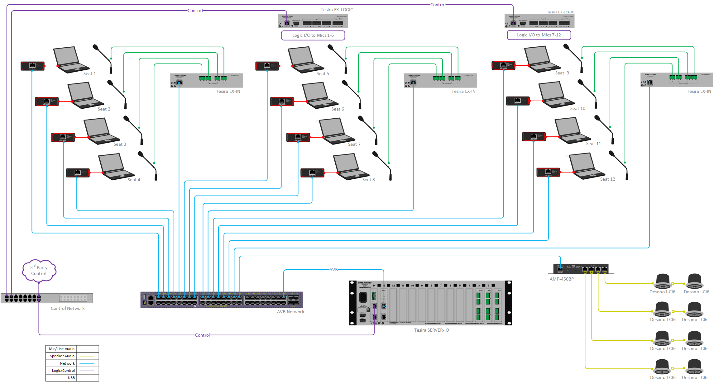
The following room design assumes a conference room with support for up to 12 local participants, but it can be easily scaled up or down for larger or smaller rooms.
Room design
Room Functionality Scope: 
- 12 Table Microphones with push-to-talk functionality and LED mute status feedback from system.
- 12 USB connections to local PC's for soft codec UC calls
- Optional system control via third-party control
- 8 ceiling speakers for playback of voice signals (UC client)
Equipment list
Below is the list of Biamp equipment used in this project:
- 1 - Server-IO AVB SEC-4(3), DSP-2 (1): 12 mic/line inputs with AEC, digital I/O over AVB
- 2 - Tesira EX-LOGIC 16 total logic connections per unit can be used as inputs or outputs for microphone mute and LED integration, PoE-powered
- 3 - Tesira EX-IN 4-channel mic/line level input expander, AVB, PoE-powered
- 12- EX-UBT Up to 8 channels of configurable USB audio in both directions, with support for Bluetooth wireless technology, mute sync and AEC offloading w/MS Teams Rooms & Google Hangouts Meet systems
- 1 - Tesira AMP-450BP 4-CH PoE+ backpack amplifier providing 4x 50 Watts burst power with RJ45 speaker outputs designed for use with Desono C-IC6 speakers
- 8 - Desono C-IC6 Wide coverage ceiling speakers (dispersion angle of 130°) optimized for voice reproduction
Note that other non-Biamp equipment is required, including the table microphones, AVB-capable network switch, and control network switch. For applications where there are 8 or fewer positions, a TesiraForte VT AVB may be substituted for the Server-IO AVB. Refer to the Tesira device count limits article for more info on number of devices that can participate in a single Tesira system.
Example Files
The example file for this system design template is set up with all the audio I/O, processing, and control points required, and is ready to load to the system and begin setting up the room gain structure. The SEC-4 cards in Server are being used to to support AEC processing for the EX-IN microphone inputs from remote expanders.
The audio component to this solution is quite sophisticated so great care must be taken to adhere to the concepts presented here for a successful deployment. This includes both the programming and commissioning phase as well as the day to day use in meetings.
Each position at the table is equipped with a dedicated gooseneck microphone for capturing the audio of each participant with a high degree of audio isolation from next adjacent participant. Speakers dedicated to each participant are not required with common ceiling speakers being frequently used.
The mixing system in the Tesira detects which local participants are speaking and when the far end is active. When a local participant is active, the audio from the room (primarily their dedicated microphone) is sent exclusively to the USB interface of their position and thus is only transmitted to the far end using their UC client. The cloud-based bridge receives that audio and replicates it to all other UC clients in the meeting (local or remote). The far end audio to be distributed in the room’s speaker system is sourced from the active microphone position’s UC client exclusively. If the far end speaks, no routing changes occur in the local room. If a new local talker begins speaking, the local room’s audio transmit and receive are switched to that position. The UC bridge hear that a new UC client is active and will switch the video focus/shot to that UC client which has the local camera attached and framing the participant. For UC platforms that feature automatic transcription, the changing of the video focus also allows the transcription to be associated with that specific UC client which would typically be labeled with the participant's name for ease of identification. This process continues over and over during the duration of the meeting.
The example file also contains all the required logic to allow for proper participant tracking and management of far end audio. Each section of the file contains a description of the functionality within. Presets for all required functionality have been added to the example file.
The .tmf file below ins the example Tesira configuration files for this conference room application.
File Download: Multi-PC/camera conferencing - Medium Room 12P
Networking details
This application will make use of the control and AVB network interfaces of the Tesira hardware to achieve a fully functioning room environment. To get this design properly running on our hardware, we will need to prepare the control and AVB sides of the network. For a more detailed guide on how to implement in a larger range of network applications, it would be helpful to reference our Tesira Network Infrastructure article. In our application, we will approach the implementation as a smaller scale setup with separated control and AVB networks as shown in the room signal flow diagram. In this approach the EX-UBT and AMP-450BP will be discovered over the AVB connection via the AVB licensed switch. The EX-Logic expander devices will be discovered through the Control connection.
Setup Requirements:
- Control network connection via switch, direct connection, or building LAN.
- AVB capable network switch with PoE, or mid-span PoE injectors for expander devices.
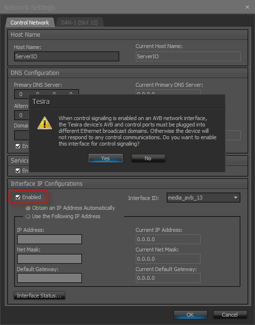
- Separated Networks mode enabled. This is done through the Network Settings button in the Device Maintenance window. The Network Settings dialog will display the settings for the Control NIC by default. In the drop down list in the Interface IP Configurations section, select the AVB media NIC. Check the Enable box to activate the IP configuration for the AVB interface. This will enable the device's AVB network interface to discover Tesira's expander and control devices. Verify that the AVB and Control networks are logically separated, and the IP addresses assigned to them must be in non-overlapping subnets. See the Essential rules section for more information on requirements when using separated networks mode.
- Units running FW 3.8 or later can also be setup using the Single Network Connection if desired.
- Note that the EX-UBT, AMP-450BP, and AMP-450P use Layer 2 AVB for audio and control data, IP address setup is not required
After these control and AVB network setup steps are complete, you will now be ready to send your compiled system configuration to the hardware.
Note: This application example can also be setup with converged or single cable networks if required.
Audio and logic setup
- Follow Gain Structure best practices to set input and output levels of microphones and sources. Input and output gain levels have been left at default settings for integration flexibility of the file. Input and Output metering has been added to assist with setting gain structure within the file. Additional meters can be added to the file as required to allow for additional detail at point along the signal path.
- Connect EX-UBT to PC for soft codec integration. Reference the USB interface setup document if needed.
- Reference AEC best practices documentation and begin to do some test calls with the system. ERL values between 0dB and +15dB are optimal.
- The example file contains all required presets to for the example application.
- Each section of the example Tesira file is defined below with a description of functionality that it adds to the design.
- In-Room microphones section manages in-room mic muting and mixing. Mix logic from this is used in other sections.
- UC Transmit manages which UC will transmit the microphone audio from the room to the far end. The Logic Delay is used to ensure audio sent to the far end is seamless
- UC Inputs supports the incoming far-end audio from each UC client. Each EX-UBT block will report logic high from its available connected, streaming, or muted states
- UC Speaker Volume and Mute manages the speaker output of the UC client. Each seat will have a "SeatXX Defaults" preset with block specific parameters and a common preset called "Seat Default Blank" to allow the primary preset to retrigger multiple times.
- UC Receive manages the incoming audio from the far end. The Switch-In Delay (typically 400ms) delays the switch till the full trip time of the UC call (to/from the UC bridge) has come back into alignment with the room. The Switch-Out Delay (typically 200ms) is coordinated with the switch-in delay.
- Privacy Control coordinates the mute requests coming from the UC clients and the microphone button presses. All mutes are synchronized. The Logic Output block drives the LED color of the microphones.
- Outputs in the section send in-room microphone audio to the far end via EX-UBT's. The mute logic (privacy) coming from the UC client is used elsewhere.
USB setup
This design template makes use of the added capabilities of the EX-UBT hardware to allow for each participant to join UC platforms of their choice. The EX-UBT USB port acts as a client to the connected host computer. Within Tesira software, the USB can be configured to pass audio in/out to the UC client.
The example file is setup as a Mono (1 input x 1 output) with connection type as Speakerphone: Disables Computer AEC. In this mode, the Acoustic Echo Cancellation (AEC) function will be provided by the AEC block in the Tesira DSP. A control message is transmitted to the soft codec via the USB link telling it to disable its internal AEC.
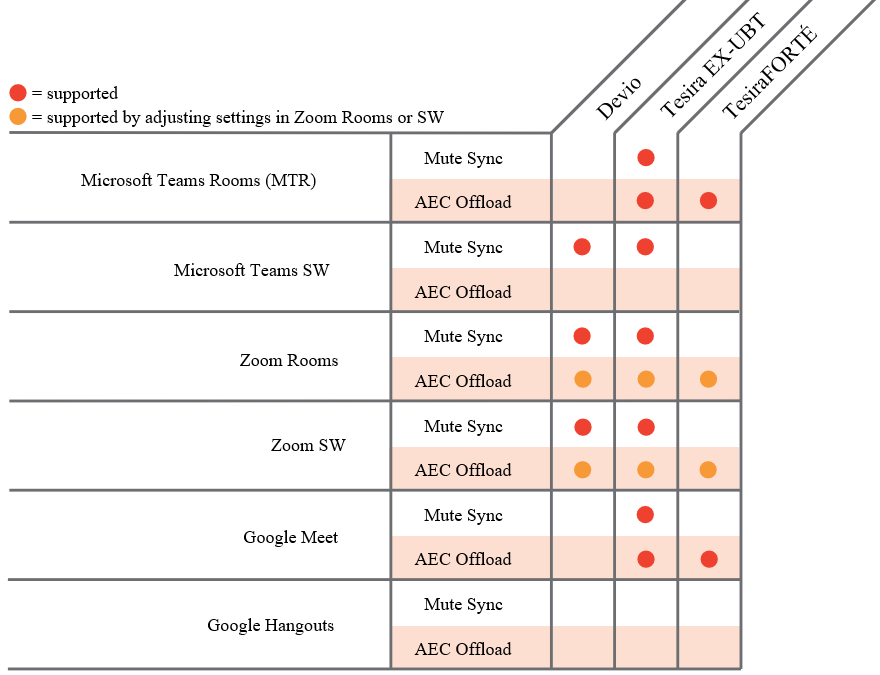
The EX-UBT USB Human Interface Device (HID) that can synchronize privacy mute state and volume control if the UC application supports this communication.HID mute synchronization and AEC offloading are supported by various UC platforms as noted:
More detailed setup and configuration info for the EX-UBT can be found in our Using the Tesira EX-UBT article.
Control integration
The example Tesira configuration file for this application file has been setup to allow third-party control systems to easily control the Tesira system. There are control points for Level control, and Mute already in place to allow for you to use as it as-is, or add to as needed to suit the needs of the client. Level controls have top and bottom limits in place that can be changed as needed for the design needs. It is recommended to limit the amount of user facing controls for the microphones in the voice lift portion to maintain proper gain structure in the system after the commissioning has been completed. Control points within the file have been noted with an additional text box showing their default instance ID tag. These tags can be changed as needed to suit the programmer workflow or standardization.
Further reading
- Tesira Network Infrastructure
- Separated or converged Control and AVB networks
- List of AVB-capable Ethernet switches
- Single Network Connection
- Gain Structure
- Room Equalization
- Tesira device count limits
- AEC
- EX-UBT Integration
- Burst Mode in Biamp PoE+ amplifiers
- Integrating desono™ loudspeakers and AMP-450P backpack amplifiers