Integrating Qt Conference Room Edition sound masking with Tesira
This article elaborates on the Qt Conference Room Edition Sound Masking product and applications, as well as provides detail on how to integrate it with the Tesira product line. If you are already familiar with the Qt Product then you may skip ahead to the section for Integrating QtCRE with Tesira.
Qt Conference Room Edition
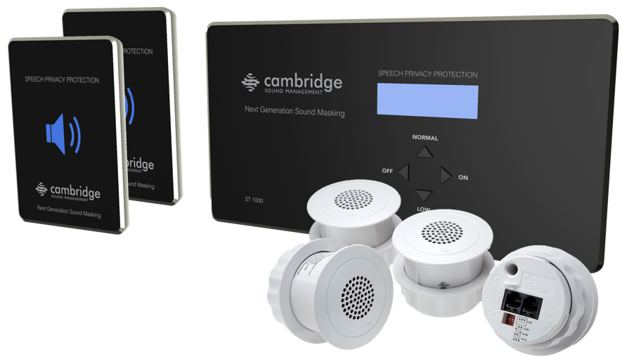
The Qt Conference Room Edition (QtCRE) is a very cost-effective solution to provide confidential speech privacy for conference rooms, executive offices and suites, boardrooms and other sensitive spaces, to the immediate areas surrounding such spaces. For convenience we may refer to all such rooms as conference rooms although that may not be their actual use. The system comprises sound masking emitters and a lighted privacy sign placed immediately outside such sensitive rooms, indicating when the system is operational, and a QtCRE controller and identical privacy sign inside the room. The system does not place sound masking emitters inside the sensitive space itself.
Using Sound Masking to Protect Privacy of Conference Rooms
The acoustical attenuation performance of walls and other construction surrounding conference rooms can vary widely. Even if high quality materials with high STC (sound transmission class) ratings are installed with the intent of providing adequate sound attenuation, the expected result may not be achieved if the surrounding space is sufficiently quiet. There may be sound leaks under doors, or HVAC that serves as “sound tubes” to adjacent spaces. Acoustical ceilings may be intended to provide good sound absorption, however, these same lightweight tiles usually allow substantial speech sound to transmit through them to plenums above, which can then find its way back down to offices adjacent the conference room. Return air grills into plenums common to both the conference room and exterior spaces are a frequent privacy issue. Background noise from a high quality building HVAC system may be so low that it provides no significant masking of speech sound escaping the conference room. The common use of modern energy-efficient variable air volume HVAC systems can further exacerbate this problem. Remedial work to the construction or HVAC system to improve privacy can be very costly, and even then may not achieve satisfactory results. On the other hand a dedicated electronic sound masking system around the conference room is cost effective and will provide confidential privacy in almost all applications.
A conference room speech privacy protection system differs from typical office-wide sound masking system in three important ways.
1. The sound masking is applied only to a select small area – the exposed area around the perimeter of the conference room.
2. Rather than operating 24/7, the QtCRE sound masking optionally may be turned on and off by users.
3. The resulting speech privacy protection status is indicated in the conference room and the entrance to it by lighted signs.
QtCRE System Planning
Sound Masking Guidelines
Generally the layout and calibration of emitters outside a conference room follow the standards for an open office design. It is important that the masking volume be set correctly to achieve the full effectiveness of the system. If volume levels are set too low, speech privacy for the conference room occupants will be reduced and people outside the conference room may find audio leakage to be more distracting. If volume levels are set too high, the masking sound itself could become a source of distraction. In a given open office design, including ceiling height, ceiling material and workstation panel height, we can define the masking volume required to achieve “normal acoustic privacy,” between offices (i.e., normal voices are audible but not easily understood). In an open office environment, the target background sound level is typically in the 45–48 dBA range, as measured 3 - 4 ft. (0.9 m) above floor level. The values provided in the table below are assuming nominal sound masking levels, although the sound masking level may be increased to provide greater privacy levels when necessary. However, increased levels can have adverse affects on user's perceiving the sound masking, and should only be increased when privacy is determined to be of utmost importance.
Ceiling Height |
Volume Level |
Intended Results (at listener ear level) |
| 8' (2.4 meters) | ≈13 - 16 | ≈45 - 48 dBA |
| 10' (3 meters) | ≈15 - 18 | ≈45 - 48 dBA |
| 12' (3.6 meters) | ≈16 - 19 | ≈45 - 48 dBA |
Emitter Layout
The goal of the system is to lower the listener’s speech-to-masking noise ratio to the point that people outside cannot understand any speech originating in the conference room, even from persons using a raised voice. Technically this is known as Confidential Privacy or having an Articulation Index (AI) of 0.05 or below and is comparable to a Speech Transmission Index (STI) of 0.12 or below. In order to achieve this goal, the emitters should be installed in rows parallel to all exposed walls of the conference room, that is, along any wall common to both the conference room and any adjacent office spaces, including open plan or private enclosed offices, corridors, storage or utility rooms, etc.
Spacing between emitters generally should follow the same rules as for other CSM direct field masking systems, i.e. Distance between emitters should not exceed the ceiling height above finished floor, and should never be more than 12 ft. between emitters. The English dimensions are based on America drop ceiling tile sizes (24x24”, 24x48”). The metric dimensions are based on international tile sizes (300x300mm).
Ceiling Height |
Spacing |
| Ceiling heights less than 10 ft. (<2.4 meters) | 8 ft. spacing (2.4 meters) |
| Ceiling height is 10 - 12 ft. (3 - 3.6 meters) | 10 ft. spacing (3 meters) |
| Ceiling heights 12 ft. and above (>3.6 meters) | 12 ft. spacing (3.6 meters) |
Controller and Privacy Sign Layout
It is important to understand how the system will be used and controlled to decide the location of the controller and privacy signs. The ST1000 controller unit is self-contained and can be operated by the end-user directly from the front panel, with the set-up features conveniently hidden from the end user to prevent accidental changes. Conversely, the system may be installed similar to standard sound masking (which is normally on 24/7), with the controller visible or hidden.
The signs indicate that the system is fully on only when lit steadily. They blink during ramping on and off (the gentle increase or decrease of sound level).
Placing the controller:
▪ This should be in a place easy to reach for occupants of the room, such as near light switches near the room entrance, or at a convenient place accessible during presentations.
▪ It can be visible or hidden, but remember people may not know how or where to operate it if its completely out of sight.
Placing the privacy signs:
▪ Two privacy signs are provided, one for the room occupants and the other for people outside the room. Typically one sign is mounted inside the conference room to alert the occupants to status and the other is mounted outside conference room, adjacent to the main door.
▪ Alternatively, the use of both signs is not required, or both may be installed inside or outside the room. It is good practice to coordinate with the Owner.
Controller Interconnects
Contact Closure: Optionally the system can be controlled via contact closure - such as Tesira GPIO configured as a logic output. Contact closure ramp speed can be set separately from front panel control ramp speed. It's worth noting that the contact closure takes priority over the front panel control settings, in which case the controller may need to be placed out of the way, such as in a closet or IT closet, to reduce any confusion about the active control point. An external contact closure can also be used to allow control from a remote switch such as a light switch or single-pole, single-throw (SPST) low voltage switch. Note that in an operating scenario in which contact closure is used, emergency cutoff can only be achieved if the low level is MUTE and CC ramp down time is 0.
Trigger Output: The trigger output provides nominally 5VDC when the system is operating at Normal level, for use in triggering other devices or to provide an acknowledgment signal back to an external control system. Note that upon initiation of a downward ramp event, deactivation of the trigger signal will lag the completion of the downward ramp by several seconds in addition to the ramp down time parameter configured on the ST1000 control module. During a ramp-up to Normal operating level event, the full and consistent activation of the trigger voltage may not be complete until the Normal operating level is reached. Control system programs should be written to anticipate and accommodate this behavior.
Audio Input: Optionally the QtCRE includes an audio input usable for low-level, narrow-spectrum audio playback, such as a door chime. It is not recommended to use the Audio Input for background music or paging due to the limited attainable levels at certain frequencies. Please reach out to your Sales Representative if you require either background music or paging abilities in your system. The input is fully functional regardless of front panel or contact closure control. Therefore, the system may be used for audible indications when masking is muted or off.
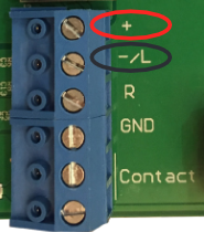
- Balanced Audio Input:
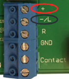
- Connect signal wires to + and - at the input. Connect the shield to GND at the audio source.
- Unbalanced Audio Input:
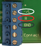
- Mono Signals: Connect the mono signal wire to both L and R (split the wire) on the block. Connect the ground wire to GND.
- Stereo Signals: Connect the respective signal wires to L and R on the block. Connect the ground wire to GND.

Integrating QtCRE with Tesira
This section details how to integrate the Qt Conference Room Edition with Tesira, and provides basic programming examples for triggering sound masking based on the state of the conferencing system.
Note: Ensure your Qt controller is working properly before integrating Tesira. Disconnect the power from the Qt controller before connecting to Tesira's Logic I/O.
Connections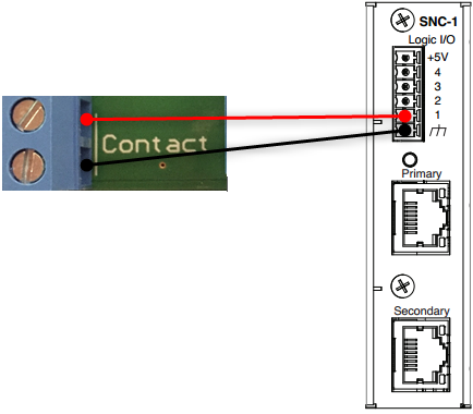
Connect the Tesira Logic I/O ground pin to the bottom contact closure terminal on the ST1000. Next, connect the top ST1000 contact closure terminal to the desired logic pin on the Tesira GPIO. Reversed polarity will result in improper operation.
Configuring the QtCRE
The contact closure can be configured to toggle between Normal/OFF or Normal/Low, and the ramp speed can be set separately from the front panel control ramp speed. To adjust these values you will need to enter the Set-up Mode of the controller by holding down the OFF and ON buttons for 5 seconds.
As previously mentioned, the contact closure takes precedence over the front-panel controls, so you may need to remove the contact closure connections in order to gain access to the front panel controls. It's also worth reiterating that the Audio Input will continue to pass signal to the outputs regardless of the contact closure state.
Programming Tesira
The Tesira Logic I/O port is an open collector type with a pull-up resistor, and this results in a +5V logic "high" when the output is NOT active. This default state will result in sound masking being off/low and the front-panel keypad being locked, however, any content brought in on the Audio Input will pass to the outputs unabated. Toggling the Logic Output block, or inverting the output within the block itself, will provide the logic "low" state that is required for the ST1000 to resume 'Normal' sound masking.
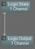
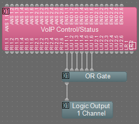
The Tesira programmer will need to provide a logic connection to the corresponding logic output block (I/O channel assignments can be made in the DSP Properties tab of the block) that is to be triggered when sound masking is needed. This could be as simple as a Logic State block that is directly controlled via third-party, or it could be more integrated to the conferencing functions and receive it's trigger from a block, such as the VoIP Control/Status' Line In Use logic output.