Council Meeting Chamber
This system design template shows how Tesira products can be used in a typical Council Meeting Chamber installation. These rooms commonly have voice-lift for the participating Council members, as well as an output to an Audio Induction Loop (also referred to as a Hearing Loop system). Traditionally, these rooms only provide local reinforcement and don't require any distant participants.
In this example, the Council Meeting Chamber is designed to include 20 table-mounted microphones, which leverage Tesira's Acoustic Echo Cancellation (AEC) to achieve optimum speech quality for the local voice lift. Each microphone has a mute button with LED, which are wired into the logic inputs/outputs in the Tesira System. Each microphone's mute control will be able to toggle through three states of Solo, Unmute All, and Mute All. The Council Meeting Chamber is fitted with ceiling speakers for the voice lift, with the ability to split the reinforcement into two separate zones for left/right, front/back, or overflow. The Tesira system will be designed with control points to allow for integration with third-party control systems for level and mute adjustments.
Room design
Room Functionality Scope:
- 20 Table Microphones with push-to-talk functionality and LED mute status feedback from system
- 70V distributed ceiling speakers for local reinforcement
- Audio Induction Loop for Assisted Listening Devices
- System control via third-party control system
Equipment list
Below is the list of Biamp equipment used in this project:
- 1 - TesiraFORTÉ AVB CI 12 mic/line level inputs with AEC; 8 mic/line level outputs; USB Audio
- 1 - Tesira EX-MOD w/ (2) EEC-4 8 total mic/line level inputs with AEC
- 3 - Tesira EX-LOGIC 16 total logic connections per unit can be used as inputs or outputs for microphone mute and LED integration, PoE- powered
- 1 - AMP-460H 4-Channel, 60W class D amplifier; supports both 70V and 100V constant-voltage speaker systems
- 8 - Community D6 Two-way, full-range, coaxial ceiling loudspeaker, 8 ohm or 70V/100V operation, 100W continuous, 250W program
Note that other non-Biamp equipment is required, including the table microphones, audio induction loop and PoE injectors.
Example files
The example file for this system design template is set up with all the audio I/O, processing, 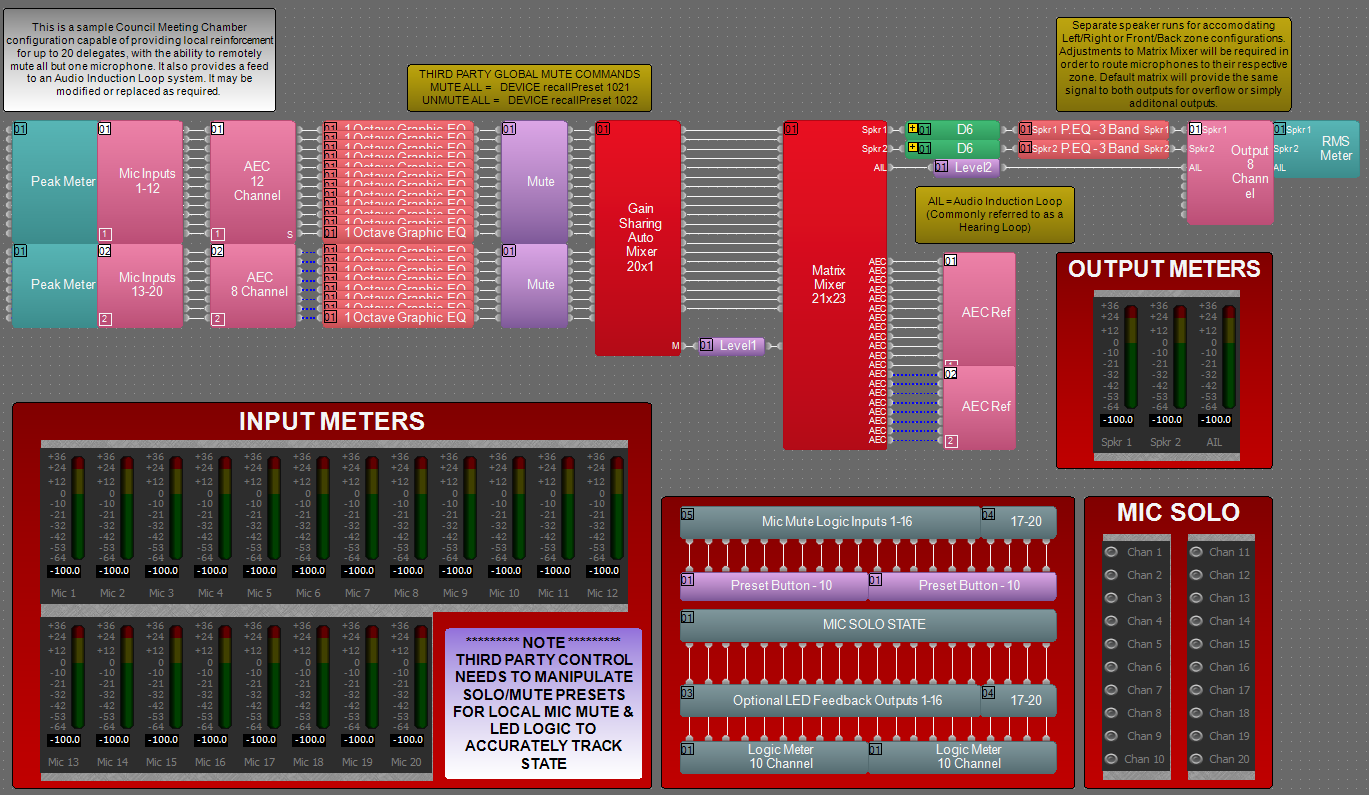 and control points required, and is ready to load to the system and begin setting up the room gain structure. In the file, the matrix routing is already in place to support the room design requirements, although outputs 1 and 2 can be modified for direct routing of specific microphones to one of two zones. All 20 AEC audio input channels, between the TesiraFORTÉ AVB CI and the Tesira EX-MOD, are used for the 20 table microphones. Outputs 1 and 2 on the TesiraFORTÉ supply a mix of the voice lift to the 70V amplifier channels and distributed ceiling speaker system. Output 3 of the TesiraFORTÉ provides a mix of all 20 microphones to the Audio Induction Loop system.
The file contains a Gain-Sharing Automixer set to the default values, however, the Microphone Isolation Factor can be modified to allow either more gain to be applied on more confident channels, or to equalize the gain provided to each channel. Additionally, presets give each user the ability to perform Solo, Unmute All, or Mute All functions of the table microphones by simply sending a momentary logic pulse from the Mics. All AEC references have been made in the Matrix Mixer to allow for proper echo cancelation of the other reinforced microphones. The file's Equipment Table is populated with proper hardware to match the layout, but will need to have serial numbers and proxy host assignments added before loading the file to system.
To assist with deployment and commissioning of systems which include the Community D6 ceiling speakers, a Tesira Library File (.tlf) has been created. This includes custom blocks with Biamp's recommended EQ curves to optimize the sound the included loudspeakers in this design. The custom blocks have been included in this system design template file. These blocks can also be found in the Processing Library in Tesira software.
The .zip file below contains the example Tesira configuration files for this Council Meeting Champer application.
File Download: Council Meeting Chamber.zip
Networking details
The Council Meeting Chamber application will make use of the control and AVB network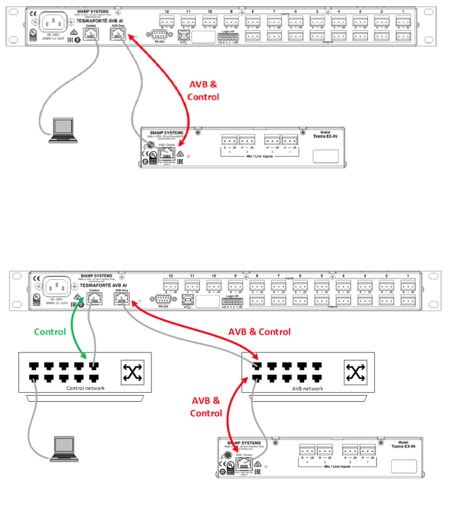 interfaces of the hardware to achieve a fully functioning room environment. To get this design properly running on our hardware, we will need to prepare the control and AVB sides of the network. This system is small enough to be placed on a very small local AV switch with direct AVB connections between devices, but is also equally capable to be integrated into a larger building network sharing larger switches for the control and AVB traffic. For a more detailed guide on how to implement in a larger range of network applications, it would be helpful to reference our Tesira Network Infrastructure article. In our application, we will approach the implementation as a smaller scale setup with separated control and AVB networks as shown in the diagram. In this approach the audio expander device will be discovered through the AVB connection rather than through the control network connection.
Setup Requirements:
- Control network switch with sufficient ports
- Direct network connection between EX-MOD and TesiraFORTÉ AVB ports (or, optionally, an AVB-capable network switch).
- 802.3af (Class 1) PoE injector for powering the EX-LOGIC (unless the Control switch provides PoE power).
- Separated Networks mode enabled. This is done through the Network Settings button in the Device Maintenance window. The Network Settings dialog will display the settings for the Control NIC by default. In the drop down list in the Interface IP Configurations section, select the AVB media NIC. Check the Enable box to activate the IP configuration for the AVB interface. This will enable the device's AVB network interface to discover Tesira's expander and control devices. Verify that the AVB and Control networks are logically separated, and the IP addresses assigned to them must be in non-overlapping subnets. See the Essential rules section for more information on requirements when using separated networks mode.
After these control and AVB network setup steps are complete, you will now be ready to send your compiled system configuration to the hardware.
Note: This application example can also be setup with a converged network if required. If this method is used, an AVB
capable switch will be required for AVB and control traffic between devices, and the AVB ports on the devices will not
need to have an IP address assigned to them.
Audio setup
- Follow Gain Structure best practices to set input and output levels of microphones and sources. Input and output gain levels have been left at default settings for integration flexibility of the file. Input and Output metering has been added to assist with setting gain structure within the file. Additional meters can be added to the file as required to allow for additional detail at point along the signal path.
- Select constant voltage(CV) and bridging on amplifier channels as needed to support room speaker topology.
- Reference AEC best practices documentation. ERL values between 0dB and +15dB are optimal.
- Level and mute controls have been added to the file pre and post matrix mixer. These are added for flexibility to meet the design criteria and tastes of the client or integrator. These level controls have been left with their default maximum and minimum values in place, but can be adjusted to fit the needs of the space.
- Graphic EQs have been added to all signal paths to allow for any additional equalization as needed to sources. It is recommended to use the advanced filters section of the AEC channel processing block for for any high pass filtering needed on conference table microphone inputs. Additional filtering or dynamics blocks may be added or changed as needed to achieve the desired results in the file.
- Parametric EQs have been added to the Speaker outputs to allow for Equalizing the system speakers.
- Changes to the matrix mixer can be made as needed to allow for appropriate sources to feed particular outputs.
Microphone mute button and LED logic
For microphone control, we are assuming the microphones in use have following features: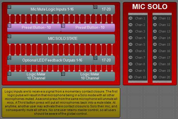
- Mute button (setup for "momentary" functionality)
- LED ON for Mic Active indication
- LED OFF for Mic Mute indication
Depending on the power requirements of the LEDs, an external power supply may be required.
Each microphone will require 2 GPIO pins, one for each feature. With 20 Microphones, we require a total of 40 pins. The three EX-LOGIC expanders with 16 pins each can provide 48 pins. The TesiraFORTE has 4 GPIO pins, giving a total of 52 GPIO pins in the system. Note: EX-LOGIC I/O 13-16 and TesiraFORTÉ GPIO are not capable of sinking voltages greater than 4V and must use an external relay, hence the reason for skipping outputs 13-16 on the second EX-LOGIC, in the event an external relay is not attainable.
Logic I/O Unit and Channel Assignments
EX-LOGIC (Device ID 03)
Channels 1 - 16 connect to Mute Buttons for Mics 1 - 16
EX-LOGIC (Device ID 04)
Channels 1 - 4 connect to Mute Buttons for Mics 17 - 20
Channels 5 - 12 connect to LEDs for Mics 1 - 8
EX-LOGIC (Device ID 05)
Channels 1 - 12 connect to LEDs for Mics 9 - 20
For details on wiring the microphone's mute button to the EX-LOGIC, see Wiring switches to the EX-LOGIC. For details on wiring the LEDs to the EX-LOGIC, see Wiring LED's and relays to the EX-LOGIC.
Control integration
Control System Integration: The example Tesira configuration file for this application file has been setup to allow third-party control systems to easily control the Tesira system. The third-party control system requires recalling Presets for control of the Mic Solo/Mute states, so that the Mic Mute buttons stay in sync with the LED state.