Installing the Devio Ceiling Microphone (DCM-1)
Below are instructions for installing the Devio Ceiling Microphone (DCM-1). Up to two DCM-1 devices can be daisy-chained and connected to a single Devio.
Installing the DCM-1
The Devio SRC-20C and SRC-25C packages include the Devio (main unit) and DCM-1 microphone. The DCM-1 consists of a single, beamforming pendant microphone and a plenum-rated box containing additional electronic components and connections. While specific installation details may vary depending on the room layout and ceiling design, general instructions are provided below for assembling and connecting the DCM-1.
- Remove the pendant microphone, plenum box, and related components from the DCM-1 box found within the Devio package. Remove the lid from the plenum box.
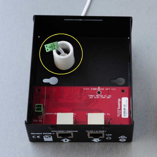
- At the end of the pendant mic's cable is a green, two-pin Phoenix connector. Around the cable is a white bushing. If the plenum box will be positioned above a ceiling tile, it will be necessary to drill a hole in the ceiling tile through which the mic cable and bushing can be passed to enter the plenum box. The ceiling tile hole should be 7/8" (22mm) in diameter.
-
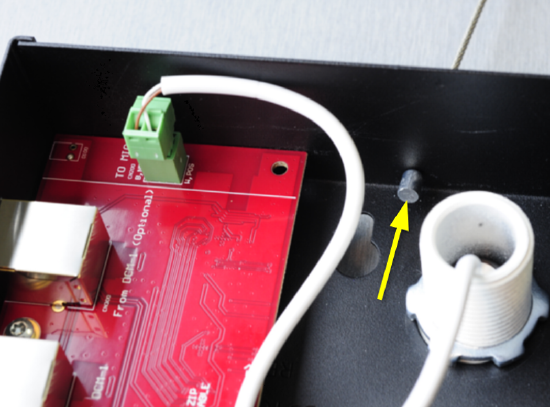
Pass the mic cable and bushing through the hole in the ceiling tile (if present), and into the circular hole in the bottom of the plenum box.
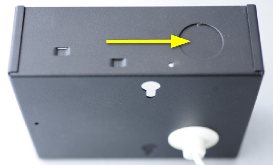
NOTE: If the plenum box needs to be mounted on its side, there is a break-away tab that can be pressed in and removed in order to provide an alternative opening for the bushing on the side of the plenum box.
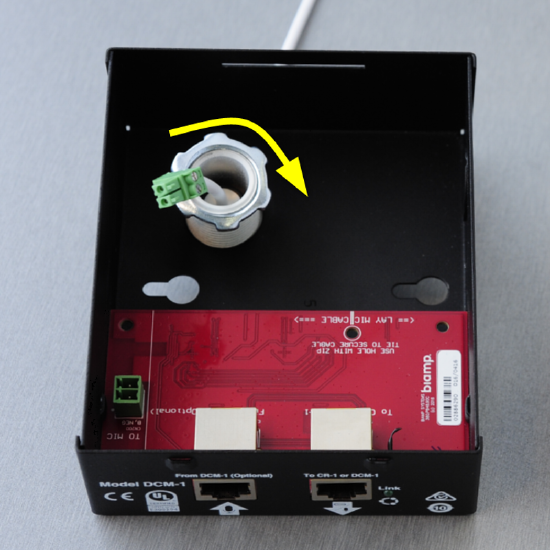
- Pass the included lock nut over the mic cable and attach to bushing. Rotate clockwise until bushing is secured to the plenum box.
- At the bottom of the bushing, which should now be secured to the bottom of the plenum box, there is a height adjustment assembly. By squeezing the divots on either side of this, the mic cable can be adjusted up and down.
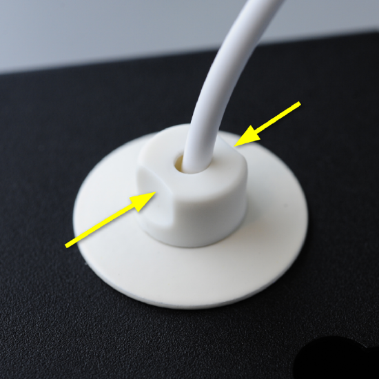
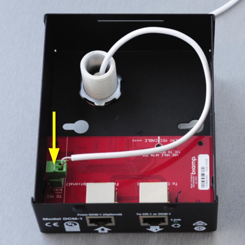
Squeeze the height adjustment assembly and pull the mic cable through the bushing until the green Phoenix connector can be connected to the microphone jack on the plenum box's circuit board. Connect the Phoenix connector to the microphone jack.

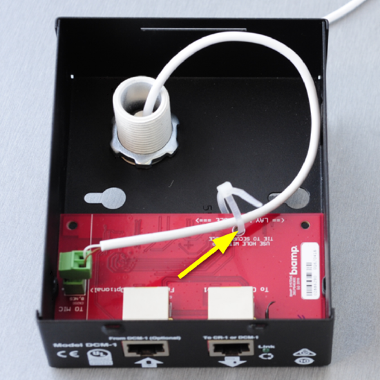
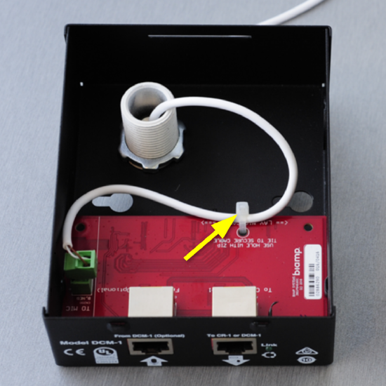
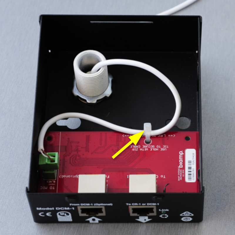
- Provide some additional slack for the mic cable inside the plenum box and lay it parallel against the edge of the plenum box's circuit board. Using the provided strain relief cable tie, secure the cable to the circuit board.
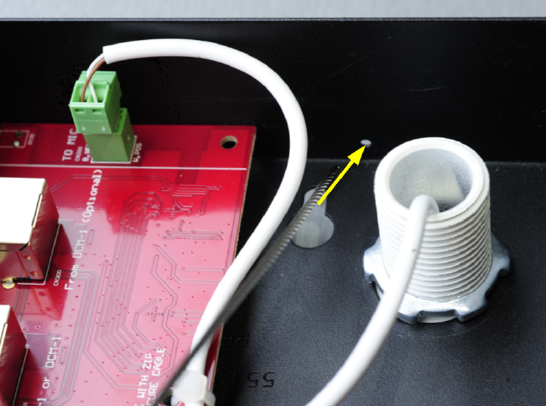
- There is a silver seismic cable provided with a cylindrical anchor on one end. Pass the unanchored end of this cable through either one of the two seismic cable holes on the sides of the plenum box so that the anchored end of the cable stops against the inside of the plenum box.
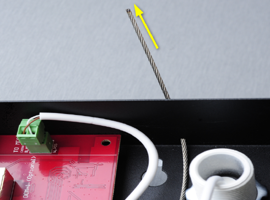
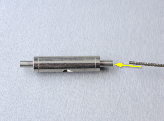
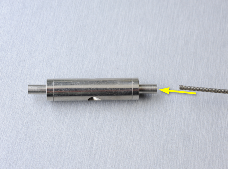
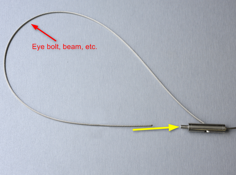
- Also provided is a silver, double-ended barrel that serves as the seismic cable tensioner. Pass the unanchored end of the seismic cable through one end of this tensioner and pull the cable through the center of the tensioner. The seismic cable can then be passed through an eye bolt, around a beam, or otherwise connected to a structure that can support the weight of the plenum box in the event of an emergency.
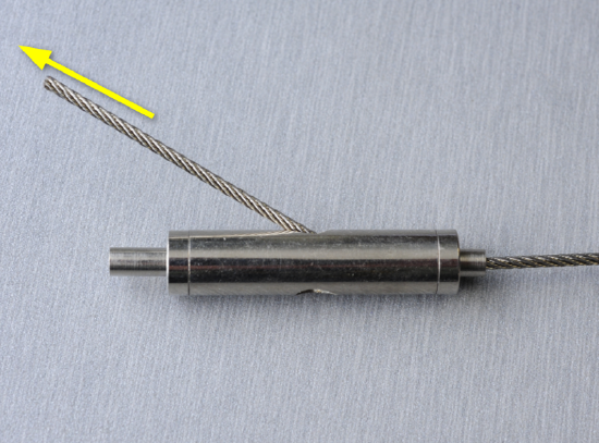
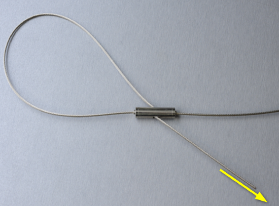
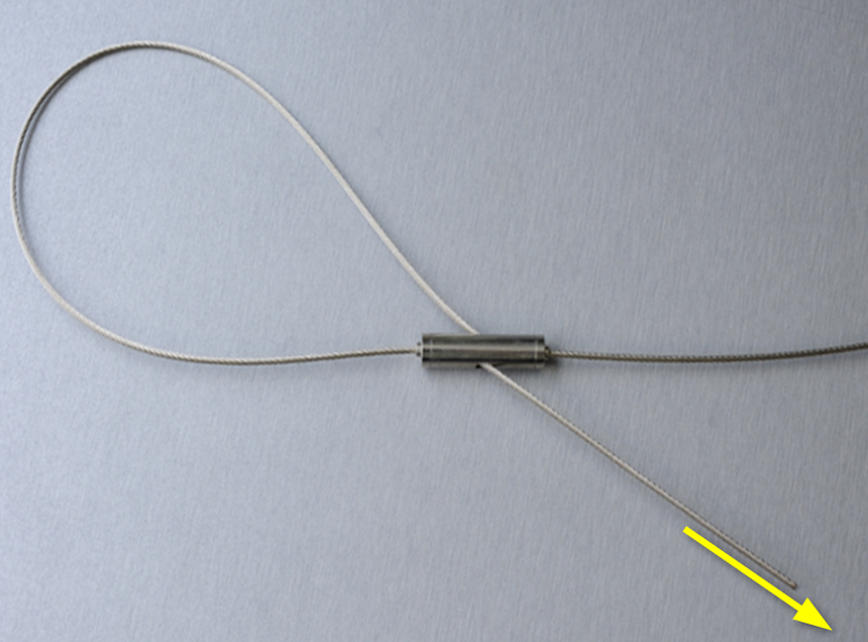
- Pass the unanchored end of the seismic cable through the remaining open end of the tensioner, then pull the seismic cable through the remaining center hole of the tensioner to tighten.

Note: If you need to loosen or remove the seismic cable from the tensioner, press in on the smaller cylinder on the end of the tensioner and then pull the seismic cable through in reverse.
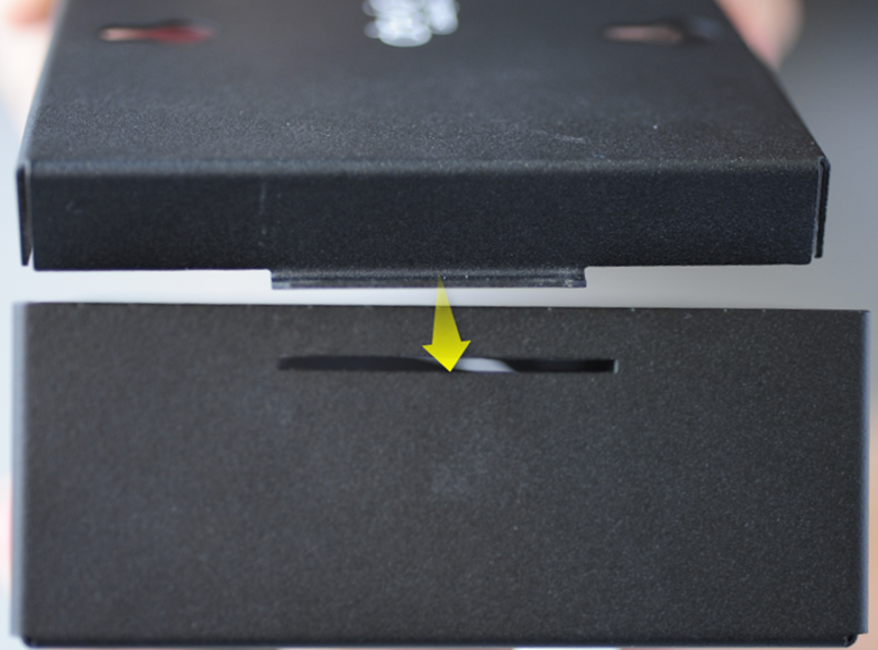
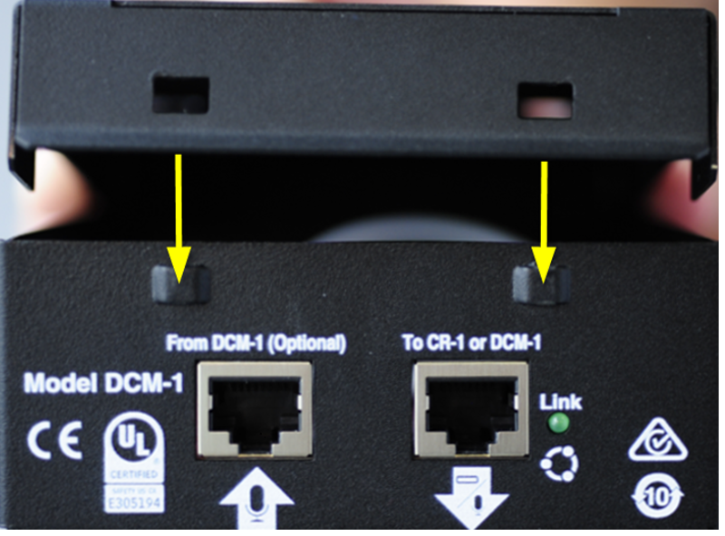
- The plenum box lid has a tab on one side. To close the plenum box, slide this tab into the hole at the back of the plenum box (the side farther from the RJ-45 ports), then press down on the opposite end of the lid to snap it into place.

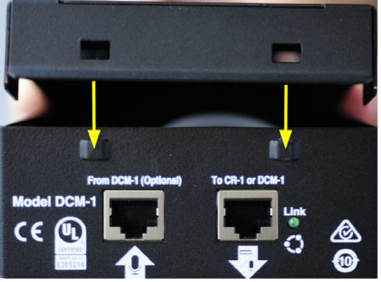
If needed, reverse this process to reopen the plenum box.
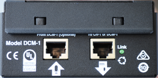
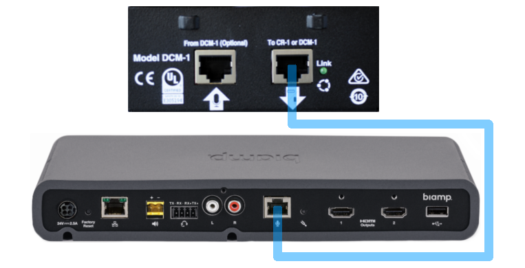
- Connect the plenum box to the Devio system via straight-through, unshielded CAT-5e or better cable. Connect one end of this cable to the "To CR-1 or DCM-1" port on the plenum box, and connect the other end to the microphone port on the Devio.

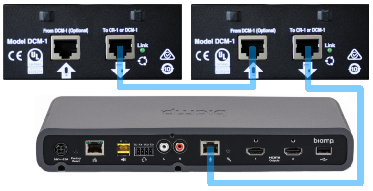
If a second DCM-1 is being added to this system, connect one end of a straight-through, unshielded CAT-5e or better cable to the "To CR-1 or DCM-1" port on the second DCM-1's plenum box. Connect the other end of this cable to the "From DCM-1 (Optional)" port on the first DCM-1's plenum box.

Cables should not exceed a maximum of 15 meters (~49ft) between any two RJ-45 microphone ports (whether plenum box to plenum box or plenum box to Devio).
Note: It is not possible to connect both a DCM-1 ceiling mic and a DTM-1 table mic to the same Devio system.
- Squeeze the height adjustment assembly and push or pull the pendant mic's cable until the microphone is at the desired height. For assistance with determining the best hanging height for this, please see the article on Positioning Devio microphones.


Configuring the DCM-1
Once the DCM-1 has been installed and connected to the Devio, it is necessary to select the correct elevation angle range for the microphone within the Devio System Administration Utility (SAU) software. This ensures optimal performance of the DCM-1's beamforming technology. The below steps will demonstrate how to configure the elevation angle in the Devio SAU.
- Connect to Devio in the SAU.
- Double-click on the device in the device list to open its control options.
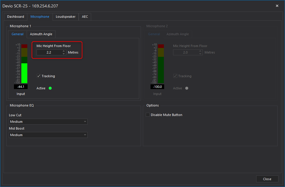
- The Mic Height From Floor should be set at the measured distance from floor to microphone array. This will affect the maximum upward angle at which the microphone will track. A higher setting will limit the angle, keeping the beam from tracking too close to sources coming from the ceiling. A lower setting will increase the coverage angle to accommodate talkers being nearer to the mic's 0° elevation angle.

-
Height AFF Min Elevation Tracking Angle Max Elevation Tracking Angle < 1.5 m (5 ft) 0° 15° 1.5 m (5 ft) 0° 30° 1.7 m (5.6 ft) 0° 45° 2 m (6.6 ft) 0° 60° 2.1 m (6.9 ft) 0° 75° 3.2 m (10.5 ft) 15° 75° 4.2 m (13.8 ft) 30° 75° 5.1 m (16.7 ft) 45° 75°
- The changes will automatically take effect after a few seconds. Click "Close" to close the control options dialog.
The angle in question is the angle from the average talker's mouth to the bottom of the DCM-1. For more information on this, please see our article on Positioning Devio microphones.
Completing the installation
Once the DCM-1 installation and positioning configuration are complete, and a loudspeaker has also been installed, perform Auto Setup on the Devio system.