Qt X Configuration using the Qt X software
Overview
This article covers a generalized workflow for configuring, commissioning, and updating a Qt X sound masking system using the Qt X system software. This includes:
- Adding devices to a new or existing system
- Assigning zones
- Configuring audio inputs
- Programming logic I/O
- Tuning outputs
- Scheduling a system soft start
- Updating firmware
- Applying security settings to a system.
- All settings and features available through the software
The Qt X family of products can also be configured and commissioned using the web interfaces onboard the devices.
Designing a Qt X System: This article does not cover the design or installation of a Qt X system from layout and coverage. However, it does outline setting up zones and loading a configuration to a controller or group of controllers.
For more complex systems consisting of larger spaces and floors or to address other complexities, contact Biamp's CSM design team to assist with generating a layout and materials list. The design team can be reached using this link to request assistance with a design quote.
Getting started
Downloading the software
Download the latest version of the Qt X Software here. The release notes for the Qt X software and firmware can be viewed here. It is important to become familiarized with the Design Interface of the software.
Factory configuration
All Qt X hardware ships with a default 1:1 zone configuration loaded. This is also the default configuration that loads after a factory reset procedure. This configuration must be cleared from all controllers before the controller blocks in a file can be assigned to physical devices using the Qt X software.
The design file may be programmed prior to installation with hardware assignment added as a last step once all Qt X controllers are available on the network.
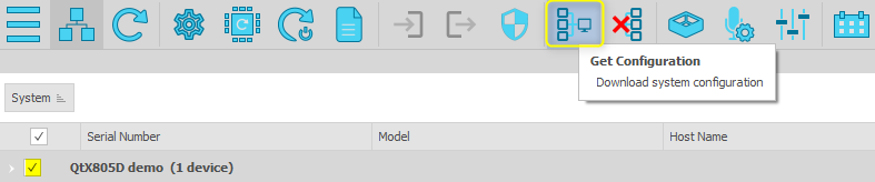
Important: When updating an active system or adding devices to an already deployed configuration file, Biamp recommends using the Get Configuration option under the Devices & Systems tab to ensure the version being updated is the current running configuration.
Configuring a Qt X system
The steps below are a suggested workflow for configuring a new system with one or more Qt X controllers. This workflow can be changed for user preference.
Note: This workflow assumes the default factory configuration has been cleared from all controllers in the system. The controllers must be in an unconfigured state in order to assign physical devices to your system using the Qt X software.
Step 1: Import a floor plan or add floors (Optional)
A Qt X system starts with a generic single-level floor area to be divided up into sound zones. The Qt X software has two options available for replacing or changing this default floor setup.
Importing a floor plan
Images of building floor plans where the sound masking 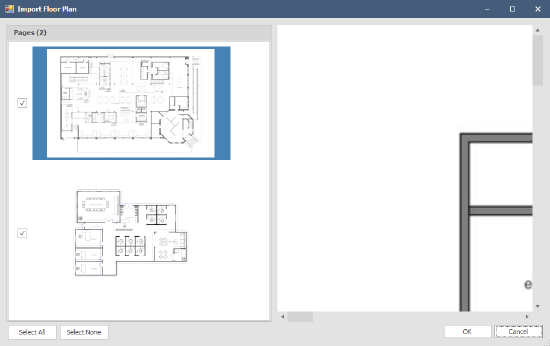 system will be installed can be imported into the Qt X software system. The image file must be in a common format (.bmp, .jpg, .png, or .pdf) and multiple pages will be imported as separate floors in the software. To import, navigate to Floors > Import Floor Plan... and select the file from your computer. Once the floor plan is imported, you can rename the floor in the Properties sheet for ease of use. If the floor plan image needs to be changed, you can update it under the Floors menu.
Note: The floor plan image cannot be resized at this time.
Adding additional floors
Multiple floors may be added to the system configuration by navigating to Floors > Add. Floors can be deleted, hiden, and unhidden using this menu. The name, background color, and grid color for each floor can be changed in the floor's Properties window.
Step 2: Zones
 Creating Zones
Once the floors covered by the sound masking system are in place, it is time to add sound zones. Start by clicking on the Add Zone icon  or using the Zones > Add menu option.
Zone placement and properties
The placement of zones on the floors in the Qt X software has no impact on system performance. However, overlaying zones on floor plan images or otherwise accurately placing them in relation to one another provides a visual map useful for both designing and servicing the system.
- Each zone is represented as a rectangle. These can be resized as needed but the shape cannot be changed.
- Zones can overlap. The most recently created zone will be on top.
- Once a zone has been added to the system, It can be resized and properties including the zone name, color, and opacity can be edited in its Properties window.
Zones created in the layout are shown in the Zone tab. Zones are named Zone1, Zone2, Zone 3, etc. in order of creation. Changing a zone name in the Properties window also changes the name on the Zones tab as well as the graphical zone on the floor plan.
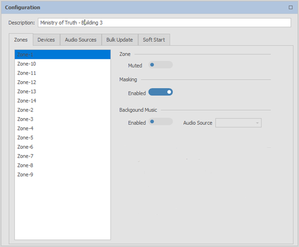
Managing zone settings
The zone management options on the Zone tab allow an entire zone to be muted as well enabling and disabling sound masking and background music in the zone. Level controls for the three possible source types (masking, background, and paging) are located toward the bottom of the tab. Each zone's setting can be changed independently based on sound management requirements in the Zone.
See Step 5 for configuring audio sources.
Step 3: Adding controllers, speakers, outputs
Adding the controllers
Controllers can be added to the system once the zones have been added and placed in their relative configuration. The controllers are added and placed 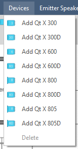 on a per-floor basis - a single controller cannot control outputs across multiple floors in the system design.
To add a controller to the system, select a controller type from the Devices list. The Qt X 300, 600, 800, or 805 models are available or their D-variants for Dante-based systems. Then place the controller outside the Zone it will control devices in.
After the controller has been placed, its properties such as the name, color, and physical device assignment can be edited in the Properties window. Controller assignment can be performed at any time in the configuration process but must be done before sending the configuration file to the system hardware. This allows for a .qdd file to be set up prior to the physical installation of the system's devices.
Adding speakers
Once the controllers are placed on each floor, select the speaker icon  to place speakers in the Zones. The same speaker object is used regardless of the speaker type in the run. Only one speaker per output needs to be added, as it represents a full line of speakers. See the Qt X Speaker Emitter article for speaker limitations in each run or output.
Assigning outputs
After the emitters are placed, connect them to the appropriate output on the Qt X controller in the system layout. Specifically, the controller that the line of speakers will physically connect to during the hardware installation. Outputs from different controllers can be used for different speaker runs in the same Zone.
Devices added to the system design can be configured in the Configuration window by selecting the Devices tab. The tab shows the list of devices placed in the layout. Additionally, the Logic I/O ports can be configured under this tab (Step 4 in this article), the analog input settings adjusted (Step 5), and the outputs of each controller configured (Step 6). The Output section of the tab lists the zone that each physical output of the controller connects to.

Step 4: Configuring logic I/O (optional)
The Logic controls are used to assign general input-output ports to functions (GPIOs). The logic functions consist of four inputs and two custom input or output ports that can be configured in a variety of ways.
- GPIO (IO1 & IO2). These act as configurable input or output signals enabling the Mute, Push to Talk, and Logic Page input functions as well as the Mute and Talk Now output functions.
- Emergency Mute (Contact 1). When an incoming signal is closed (Active Low), all sound masking zones, background music sources, and paging will be muted.
- Dedicated Push to Talk (Contact 2): When an incoming contact is closed (Active Low), the audio source shown will be sent to all zones selected in the Zone drop-down. This will mute any background music in the selected zones.
- Privacy 1 & 2. These light panels indicate the sound masking status. They do not have any audio functions nor any priority to ensure the Privacy Light indicators cannot be overridden. Privacy Lights may only be set to activate or not.
If any of these features are used, the port can be assigned to the relevant zone(s) and the two custom ports can be set to Mute or Talk Now when assigned as an output, or Mute and Push to Talk on an input. GPIO ports can also be set to Active Low if the logic signal needs to be inverted.

Step 5: Configuring audio sources(optional)
The system allows for input of background music, paging signals, or other audio sources into the Qt X system via three methods: analog inputs or an AVB or Dante network. Analog input settings such as phantom power and preamp gain can be set in the Devices tab.
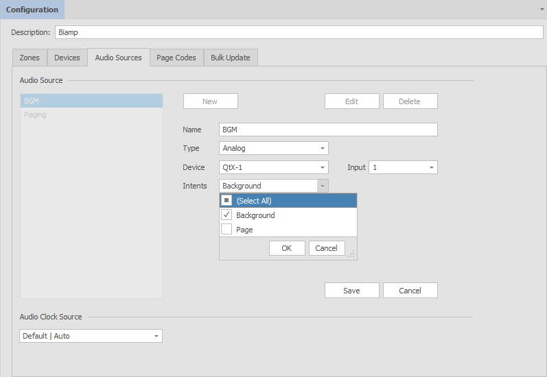
The Audio Sources tab allows you to create different audio sources and assign the input methods. Each audio source can be named, and the input can be configured regardless if it is AVB or Dante. For analog inputs, the Device and Input numbers will need to be selected. See the Qt X articles for programming AVB or Dante audio sources. The "Intents" field provides a choice of Background and/or Page. Sources with "Page" designations will be available to select from when setting the "Push to Talk" audio source.
Step 6: Configuring output settings
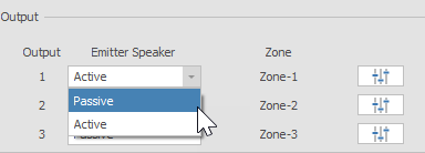
Under the Devices tab, outputs can be set between Passive or Active Emitters for the Qt X 300 and 600 models, or between DS1320s, 4 Ohms, or 8 Ohms for the Qt X 800 and 805 models. The output will show the name of the Zone it's connected to in the layout, and the  icon will open the EQ and level settings for the output. Sound masking and auxiliary signals each have their own equalizers, and Masking, Background, and Paging levels for the output can be set. The below table shows which Speaker/Emitter types can be assigned to which devices.

| Device | Speaker/Emitter Type |
|---|---|
| Qt X 300/300D | Passive/Active |
| Qt X 600/600D | Passive/Active |
| Qt X800/800D | 4/8 Ohm or DS1320 |
| Qt X 805/805D | 4/8 Ohm or DS1320 |
Step 7: Bulk update (optional)
The Bulk Update tab allows users to change input and output settings on multiple Qt X controllers within the system at the same time. On the Input sub-tab, the phantom power state and preamp gain can be changed for the analog audio inputs across multiple controllers. The Output sub-tab allows you to make adjustments to both the sound masking EQ and aux EQ settings to multiple devices rather than having to tune each output individually, though individual adjustments can still be made as necessary.
Step 8: Sending the configuration
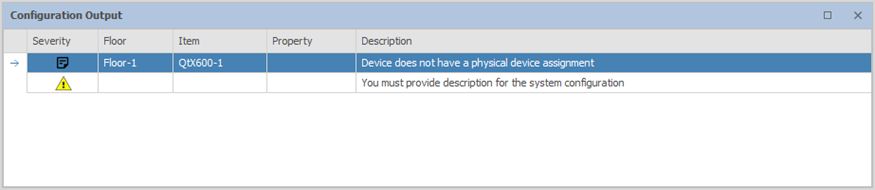
Once the system is programmed and the physical devices are connected, you can send the configuration to all the devices on the network. Click the  icon to send the configuration to the system. A pop-up window will indicate that the configuration was successfully sent or failed. The Configuration Output windows will list information and errors encountered during the system configuration. It does not monitor the system or devices in real-time, just provides context to any configuration sending failures. Devices in the software must be assigned to physical devices in the Properties sheet of each controller (Step 3) for the controller to be included in the system.
Updating firmware on a Qt X system
Qt X controller firmware can be updated using the Devices & Systems window in the software. The firmware update icon is available whether the Device or the System option is selected as long as one or more discovered devices is selected. All devices in a configured system must have the same firmware version, so devices in a system cannot be updated independently. The full system must be updated together. This ensures a configured system is not inadvertently debilitated by updating firmware on a single device. If more than 25 devices are present in a system, the firmware will update in batches (25 devices at a time.) Unconfigured devices may be updated individually if needed.
Once the desired devices are selected, click the Firmware Update icon  to select a firmware file to upload. Once you've selected the appropriate file (.qfa2 format) from the file browser, click Update to begin. A status bar will indicate progress and a dialog box will indicate when the firmware update has completed.
System Security
Qt X systems can optionally be protected by password-protected logins with permissions defined by the various user role options once a system has been configured and deployed. Under the Devices & Systems section of the software, you will have the option to protect a configured system.
To protect a system, click the Security icon  to open the Manage System Security window. When setting security levels, you will first need to create an Admin-level user. This is required for any protected system and allows for top-level control - be sure to document the admin user name and password in a secure place as it is unrecoverable if lost.
Once the Admin login is created, you will then have the option to add additional logins and assign different user roles. To unprotect a system, you will need to log in as an Admin-level user. The Unprotect System option is available in the Manage System Security window. Unprotecting the system removes all user accounts and you will no longer be prompted for login information when accessing the system. A more detailed list of permissions can be found in the Qt X Software Help System Security article.
| User Role | Permissions |
|---|---|
| Administrator | Full access - may create users, unprotect/protect a system, make changes to the system, etc. |
| Commissioner | Same permissions as the Administrator except they may not create new users or make changes to the network protocols. |
| User | Some ability to change settings, such as zones, time/date, scheduling, etc. |
| Viewer | Read-only; cannot make any changes to devices or systems. |
Certificate management
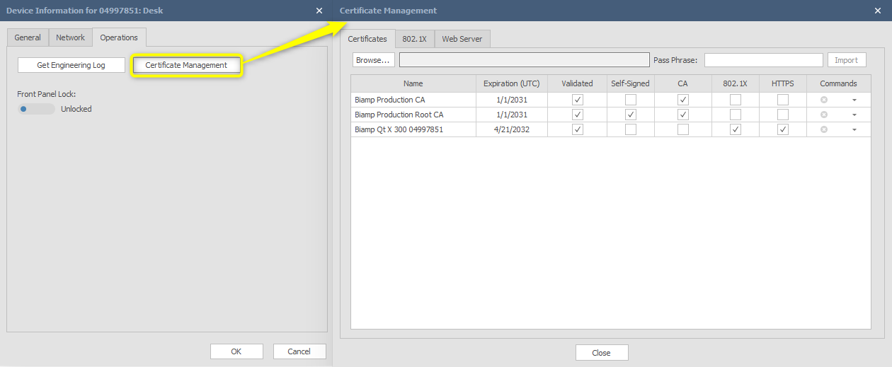
The Security Configuration dialog allows users to manage security settings such as viewing currently-applied security certificates, the status of 802.1x, and settings associated with the web server. Detailed information about viewing and applying certificates on a Qt X system can be found in the Qt X Software Help System Certificate Management article.
Certificate management is only accessible using the Qt X software application. The certificates tab is accessed from the Device Information  screen - Operations tab. Select the Certificate Management button to view and update settings.
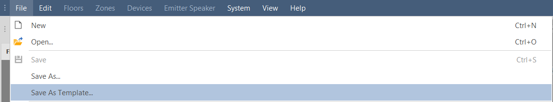
Save As Template
Save as template removes physical assignment and resets the system Id. Qt X does not support the implementation of two of the same system Ids on the same network. Another use may be that you want to use your layout at another site so you save as template in order to remove physical assignment.
Save configuration and settings report
In software version 2.5.0 and later, there is a new selection under the "File" menu that allows users to save the configuration and settings to a PDF file. If the software is currently connected to an active system, all live settings from controllers in the active configuration will be downloaded in this report for archiving.

Note: If the software is not online with a live system, the user will receive a message advising that the report will use the static data from the .qdd configuration file currently open the Qt X software. This report includes only data that is able to be extracted from the local configuration file and does not include firmware versions, or live equalization data from system.