

Divisible Conference space using dual TesiraFORTÉ X with Beamtracking Mics
This system design template shows how the Tesira Beamtracking™ microphone and EX-UBT can be used in a typical large divisible conference room installation. Traditionally, these rooms are designed to allow room participants to host local meetings with one another using local presentation capabilities, as well as make conference calls to remote meeting participants over the phone (VoIP or analog POTS), a PC-based soft codec, and even using a Bluetooth connection if desired.
In this example, the conference room will be equipped with three beamtracking pendant microphones, covering the entire seating area around the conference table. Meeting attendees will be automatically tracked and picked up by the ceiling microphones, which eliminates any user intervention. Tesira's Acoustic Echo Cancellation (AEC) technology and the TCM-1 beamtracker work together to deliver optimum speech quality to the far end participants. This rooms in this Design guide are large enough that for presentations a lavaliere mic will provide voice lift to the room, as well as an optional configuration to route the beamtracking mics from one room to the other, should the rooms be separated by some distance. Ceiling speakers are located at suitable positions to evenly cover the room with the far-end voice, USB audio, or auxiliary audio. Amplification for the speakers will be provided by the AMP-460, an affordable rack mountable amp. The TesiraFORTÈ AVB VT4 can also interface with analog telephone lines or a VoIP telephony system to allow for a voice-only telephone conference. All of this can operate one one AVB capable PoE switch, or multiple switches to allow for an interface to 3rd party control.
Room design
Each room will contain the following:
- Three ceiling mounted microphones with beamtracking technology
- Lavaliere microphones for local presentations/conferencing
- Handheld microphones for local presentations/conferencing
- Connection to VoIP system for SIP based calling.
- USB connection to local PC for soft codec from each Forte X
- Stereo program source audio inputs
- System control via third-party control system
- Ceiling speakers for playback of voice signals (UC client VoIP, speech reinforcement)
Equipment list
Below is the list of Biamp equipment used in this project:
- 2 - TesiraFORTÉ X 1600 16 AEC channels assignable to any input, 2 mic/line level inputs ; 2 mic/line level outputs, 5-port media network with 4 PoE+ capability, integrated VoIP, and 2x2 configurable USB audio.
- 2 - Tesira TCM-XA AVB beamtracking ceiling microphone
- 2 - Tesira TCM-X EX Extension beamtracking ceiling microphone
Note that other non-Biamp equipment is required, such as a wireless Dante microphones, control network switch and 3rd party control.
System configuration
The example file for this system design template is set up with all the audio I/O, processing, and control points required, and is ready to load to the system and begin setting up the room gain structure and EQing. In the file, the matrix routing is already in place to support the room design requirements. Input 1 of each AVB VT4 is dedicated to the lavaliere mic and the AEC processing of the TCM beamtracking mics has taken AEC on inputs 2,3 and 4. this frees up inputs 2, and 3 to be dedicated to the Stereo audio source s that does not require AEC. Conferencing audio is routed out to the Ceiling speaker output, while the stereo program audio is routed out to the stereo speakers in the room.
To support the conferencing needs of the space, the microphone signal is routed to the VoIP, analog telephone (POTS), USB outputs and Bluetooth. USB initialization in the file has been setup to support a 1ch x 1ch audio configuration with computer AEC disabled for the PC connection. All AEC references have been made in the matrix mixer for proper echo cancelation of conferencing sources. All conferencing devices are cross-mixed among each other to allow the use of multiple distance-conferencing methods at the same time.
To Facilitate the room combining functionality each signal is routed through room combiners. In their separated state the Audio from room A is just routed back to Room A, when combined audio from Room A is routed to both room A and B. The same is true in reverse. there is an optional signal path to route the signal of Room A's beamtracking mics to Room B's ceiling speakers and and vice versa. Note that the beamtracking mics are not intended for voice lift in a system and this path should only be un-muted if Room A is a significant distance from room B.
The file's Equipment Table is populated with proper hardware to match the layout, but will need to have serial numbers and proxy host assignments added before loading the file to system.
Even though the analog telephone interface is considered an optional method for conferencing in this design template, it can be found pre-configured in the system configuration file. Either VoIP or POTS may be used on demand to accommodate for the preferred connection method with the telephone system.
The .zip file below contains the example Tesira configuration files for this conference room application.
Divisible_Conference_Space_with_Beamtracking_Mics_&_EX-UBT.zip

Networking details
This conference room application will make use of PoE and PoE+ powered endpoints, which connect to the TesiraFORTÉ server-class device and exchange AVB audio and control data. In regards to cable types and lengths, the common rules to gigabit Ethernet cabling do apply. While the TCM-1 host microphones, can communicate via AVB only, the control port of TesiraFORTÉ but be able to see the mics. The simplest way to realize a functioning system, is using a converged network on one AVB switch as shown in the drawing above. Static IP addresses may be assigned to the TesiraFORTÉ if desired. For a more detailed guide on how to implement in a larger range of network applications, it would be helpful to reference our Tesira Network Infrastructure article.
Setup Requirements:
- Use an AVB-enabled network switch with sufficient number of ports (6) and PoE+ (IEEE802.3at) support, to interconnect all devices, including their control ports. AVB supports converged networks with no further prerequisites, however, a separated control network may be set up if desired.
- Optional: 802.3af (Class 3) PoE injector for powering the EX-UBT.
- Optional 802.3at (Class 4) PoE+ injector for powering the AMP-450P and the TCM-1.
- A standard network cable (Cat.5 or higher) to connect the TCM-1 with the TCM-1EX.
- Do not exceed 33ft or 10m on this link
- This is a proprietary digital audio link, not compatible with Ethernet
- Note that the TCM-1 mics use Layer 2 AVB for audio and control data, IP address setup is not required.
Note: This application example can also be set up with a separated network if required. If this method is used, an AVB capable switch will be required for AVB and a separate switch for control traffic between devices. In a separated network, the AVB port on the TesriaFORTE CI will need to be enabled. Please reference our Separated or converged Control and AVB networks article.
Microphone and speaker placement
The room
Arguably the single most important element in a conference system is the room itself. A noisy and reverberant room will generally sound awful for conferencing. A properly designed room with controlled reverberation and low noise floor will generally sound good for conferencing.
The importance of creating a controlled acoustic environment cannot be overstated. It is important to make the room as quiet as possible (lower noise floor) and minimize reverberance (shorter RT60) in preparation for installing the conferencing system. When properly applied, soundproofing and acoustic treatments will yield dramatic improvements in performance for most rooms.
Microphone placement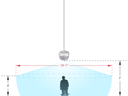
Even though the TCM-1 beamtracking microphones use state of the art technology to track a person's voice, while reducing unwanted background noise, the laws of physics can't be ignored when deciding on the right placement of a microphone. A good signal-to-noise ratio is key in every part of the audio signal chain and for a typical microphone pickup scenario, this translates to avoiding large distances between the mic and the talker. The TCM-1 Calculator will help to find the right pendant height and required distance between the two pendants for the the expected coverage area. Here are a few more tips to an ideal microphone placement:
- Keep the distance to the talker as short as possible.
- Keep the distance to the ceiling speakers as high as possible.
- Stay away from noise sources like projector fans and air vents.
Speaker placement
Placing speakers in a room can be as equally critical as finding the right spot for a microphone. An ideal positioning of multiple ceiling speakers will achieve an even SPL coverage and a good speech intelligibility across the entire room.
Audio setup
- The gain structure of the TCM beamtracking microphones is pre-configured for a room of this size but can be modified as needed. The TCM-1A amplifier may need to be attenuated if the output is too high for the room. Input and Output meters have been added to assist with setting levels within the file. You will want to make sure output levels are set at the appropriate levels for the rooms.
- Connect USB to PC for soft codec integration if required. Reference the Using the Tesira EX-UBT article for more details on working with the EX-UBT. Please note there is a 9 dBu decrement for the Bluetooh and USB inputs. This should normalize these dBFS sources to that of comparable analog inputs. Please reference our Using the Tesira EX-UB article for further details.
- The AEC Channel blocks in the software have been pre-configured for use with the TCM-1 beamtracking mics. If additional changes are needed, please reference our AEC best practices documentation and place necessary test calls with the system. ERL values between 0dB and +15dB are optimal.
- Level and mute controls have been added to the file pre and post matrix mixer. These are added for flexibility to meet the design criteria and tastes of the client or integrator. These level controls have been left with their default maximum and minimum values in place, but can be adjusted to fit the needs of the space.
- The TCM-1 beamtracking custom block has been placed in the file and is designed to get the best quality audio from the microphones. If you want to make additional adjustments please reference our TCM-1 tips and tricks article.
- Changes to matrix mixer can be made as needed to allow for appropriate sources to feed the stereo and distributed speaker zones to fit the design application.
VoIP setup
If a VoIP phone line is to be used, it must be correctly configured to register with the in-house VoIP phone system. Biamp VoIP interfaces have been tested and/or certified to work with the VoIP telephony systems listed here. Biamp VoIP interfaces may also be able to work with other SIP-based VoIP systems, but they haven't been tested or certified with those systems.
When integrating Tesira with one of the tested/certified VoIP systems, it is best to follow the detailed instructions in the appropriate article to ensure a successful deployment. Detailed instructions can be found in the following articles:
- Microsoft Lync / Skype For Business
- Cisco CallManager
- ShoreTel
- Mitel 3300 ICP configuration for a Tesira SVC-2 or TesiraFORTÉ VI
- Avaya Session Manager
- Avaya SES
- Avaya IP Office
- Avaya Communication Server
The basic steps to configure the VoIP interface start with opening the VoIP Control/Status block configuration dialog to access VoIP settings:

(Click to see configuration dialog)
There are some required fields in the Network and Protocol tabs of the VoIP Control/Status block that must be filled in correctly for successful VoIP endpoint registration:
Network Tab:
- IP Address / Netmask /Gateway - The VoIP card must have an appropriate IP configuration for the network it is connected to
- VLAN Tagging - If the VoIP card is on a "tagged" VLAN, this must be enabled and the correct VLAN ID must be provided. If the VoIP card is on an "untagged" VLAN (or no VLAN), this should not be enabled.
Protocol Tab:
- SIP User Name - This is usually the extension number that the VoIP interface will use.
- Authentication User Name / Password - The username and password required to authenticate this extension.
- Proxy Vendor - Selecting the correct vendor will ensure that the VoIP interface correctly tailors its communications to the VoIP system.
- Proxy Address - The IP address of the VoIP proxy server (also known as: VoIP server, Call Manager server).
Much of the above information must be obtained from the customer's IT or VoIP team. The following document was designed to facilitate the process of obtaining this information. Provide this documentation to the IT/VoIP team and ask them to fill it out:
VoIP Checklist Form
Control Integration
For Control Systems: Tesira systems can be accessed via Serial, telnet, or SSH depending on the networking requirements and needs of the site these settings will have to be enabled before the Tesira will be able to respond to commands. All are enabled in Device maintenance, Serial ports are enabled in the Port settings dialog, while telnet and SSH are enabled under network settings Biamp has a calculator provided on this site to allow a programmer to generate needed commands. The command string calulator can be accessed from the main Support page and can reduce the amount of time needed to generate the commands. The instance tags of all level control blocks is shown in the file.