Small hotel ballroom with TEC-X control
This system design template shows how Tesira products can be used in a small hotel ballroom room installation. A typical ballroom can be setup to accommodate distributed and/or stereo audio throughout the space from a number of auxiliary room input locations along with selectable background music sources.
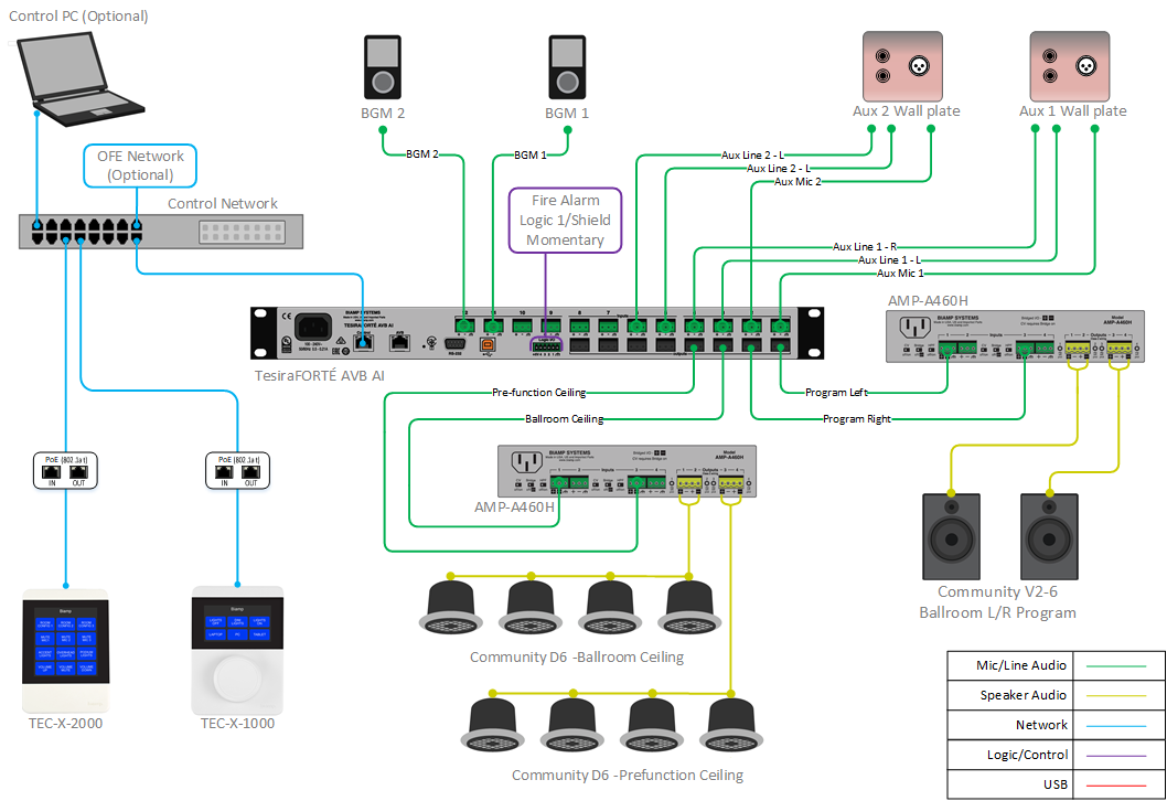
In this small hotel ballroom example, we will be setting up a flexible audio system utilizing the TesiraFORTÉ AVB AI hardware with a wall mounted TEC-X-2000 user control interface. The ballroom will consist of a single-room system with two aux wall plate locations with a mic level and line level inputs at each. These sources will be mixed together and sent to the distributed or stereo room speakers outputs as required for the specific design. There will be two background music sources available to the ballroom system with source selection and level control. The application will also include a pre-function area audio feed to distributed ceiling speakers with the ability to select background music sources, or ballroom audio for overflow purposes with a TEC-X-1000 wall mounted controller. The system can also be muted by a contact closure trigger from the fire alarm panel.
NOTE: The TEC-X details in this article apply to Tesira software version 4.4.0 or newer and Tesira Firmware Version 4.4.0 or newer. Both can be downloaded from here (the link opens in a new tab).
Room design
Ballroom Functionality Scope:
- Two auxiliary analog input locations in the room supporting both Mic or Line level signals, with available routing to either ceiling or stereo speakers.
- Two selectable analog background music inputs to system.
- 70V distributed ceiling speaker feed to support speech reinforcement and/or BGM sources.
- L/R speaker system in room to support stereo input sources.
- Ballroom level control and source select via wall mounted TEC-X-2000 wall panel.
- Pre-function area 70V distributed ceiling speaker system, with source selection of background music sources or ballroom audio via wall mounted TEC-X-1000 wall panel.
- User interface for advanced control and routing via Biamp Canvas software
- System logic inputs to trigger system mute to all areas from third-party fire/emergency contact closure.
Equipment list
Below is the list of Biamp equipment used in this project:
- 1 - TesiraFORTÉ AVB AI 12 mic/line level inputs; 8 mic/line level outputs with integrated USB audio
- 1 - Tesira TEC-X-1000 Tesira PoE Network AV Control Pad; up to 6 buttons, with rotary encoder
- 1 - Tesira TEC-X-2000 Tesira PoE Network AV Control Pad; up to 12 buttons
- 2 - PH POE36U-1AT-R Gigabit PoE+ Injector, IEEE802.3af compliant, IEEE802.3at, PoE capable network switch, or equivalent PoE injector
- 2 - AMP-460H 4-Channel, 60W class D amplifier; supports both 70V and 100V constant-voltage speaker systems
- 8 - Community D6 Two-way, full-range, coaxial ceiling loudspeaker, 8 ohm or 70V/100V operation, 100W continuous, 250W program
- 2 - Community V2-6 6-inch Compact Full-Range Two-Way Compact Point Source Loudspeakers, 100W continuous @ 8 ohms
Note that other non-Biamp equipment is required, including the microphones, background music sources, stereo program source device, network switch, and fire alarm panel interface.
Example file
The example file for this system design template is set up with all the analog audio I/O, processing, and control points required for the functionality scope, and is ready to load to the system. In the file, the matrix routing is setup for microphone inputs and nd music to be fed to the distributed speaker system while line level aux inputs are routed to the stereo speakers. These routes may be changed or mod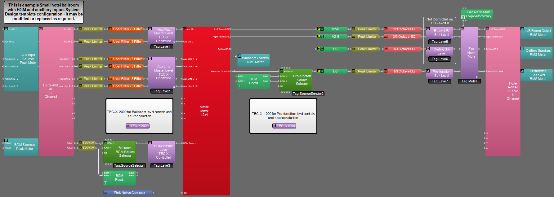 ified as needed to fit specific the design application.
The file's Equipment Table is populated with proper hardware to match the layout, but will need to have serial numbers and proxy host assignments added before loading the file to system. The file download includes an optional Canvas control file that can be used for advanced routing and control of the system if required.
To assist with deployment and commissioning of systems which include the Community D6 and V2-6 speakers, a Tesira Library File (.tlf) has been created. This includes custom blocks with Biamp's recommended EQ curves to optimize the sound of the included loudspeakers in this design. The custom blocks have been included in this system design template file. These blocks can also be found in the Processing Library in Tesira software.
The .zip file below contains the example Tesiraand Canvas configuration files for this hotel ballroom application.
File Download: System Design Template-Small hotel ballroom with auxiliary inputs, TEC-X control.zip
Networking details
The sample small ballroom application will make use of only the control network interface of the hardware to achieve a fully functioning room environment. We have included AVB capable hardware in the design to allow for future expansion, but are not implementing AVB in this application. This system is small enough to be placed on a very small local AV switch, but is also equally capable to be integrated into a larger building network sharing larger switches for control traffic. For a more detailed guide on how to implement in a larger range of network applications, it would be helpful to reference our Tesira Network Infrastructure article.
Both hardware devices will need to be discovered in Tesira software before the configuration can be sent. The PC must have a unique IP address in the same subnet as the TesiraFORTÉ device. A TesiraFORTÉ device is configured from the factory with DHCP or Zero Conf (Link Local) address. If you wish to verify your PC network interface is set correctly, please review the Setting an IP address section. More details of system connections can be found here.
Setup Requirements:
- Control network switch with sufficient ports and PoE capable port(s)
- 802.3at (Class 2) PoE injector(s) for powering the TEC-X controllers or PoE capable port. TEC-X requires 7W.
- Connection to Owner PC and network for Canvas user interface control.
- TEC-X devices need to be connected to the same network and discoverable by Tesira Software.
- Up to four TEC-X devices can be daisy chained together.
Audio setup
- Follow Gain Structure best practices to set input and output levels of microphones and sources. Input and output gain levels have been left at default settings for integration flexibility of the file. Input and Output metering has been added to assist with setting gain structure within the file. Additional meters can be added to the file as required to allow for additional detail at point along the signal path.
- Upper and lower limits have been added to level blocks for user facing controls. These can be adjusted to fit the design application as needed.
- Note that the file has two auxiliary input locations available with mic level and stereo line level inputs at each. These input types may be modified as needed to fit the space requirements.
- Select constant voltage (CV) and bridging on amplifier channels to support room speaker topology. Refer to room design signal flow diagram for more details.
- Uber Filters and Limiters have been added to all signal paths to allow for any additional equalization and signal management as needed to sources. Additional filtering or dynamics blocks may be added or changed as needed to achieve the desired results in the file.
- A graphic EQ block has been added to all speaker outputs to allow for room tuning and equalization. For a more detailed guide on room optimization, see our equalization guide. The Tesira file also includes custom blocks with Biamp's recommended EQ curves to optimize the sound the included loudspeakers in this design.
- Logic for fire alarm muting is setup to mute all audio paths for the duration the contact closure is closed. This functionality may be modified as needed to fit exact room requirements, or removed if not needed.
- Changes to the matrix mixer can be made as needed to allow for appropriate sources to feed the stereo and distributed speaker zones to fit the design application.
System control
TEC-X Setup:
Setting up TEC-X Control Pad properties is done the same way as other Tesira Remote Devices. Depending on the system, it might be necessary to adjust the network settings and change the Host Name and Device ID of the TEC-X Control Pads:
- Open Device Maintenance by navigating to System > Network. Perform Device Maintenance.
- Click Remote Devices.
- Select the TEC-X you want to set up.
- To change network Settings like Host Name and/or IP settings, click Network Settings.
- To change the Device ID, click TEC-X Properties.
Programming a TEC-X
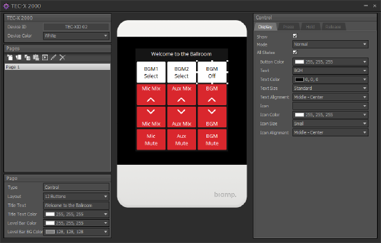
Configuring TEC-X Control Pads is done in Tesira software by inserting the appropriate block and configuring the desired functionality:
- On the object bar, go to Control Blocks and select TEC-X.
- Click anywhere on your screen to insert the TEC-X block.
- Select the Device Type and click OK.
- Open the configuration dialog by double-clicking on the block.
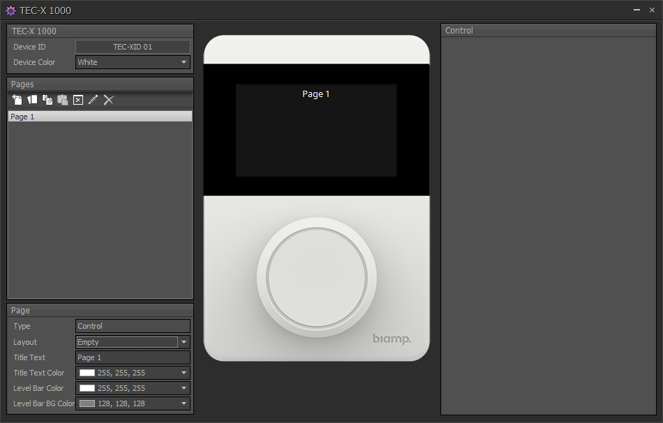
- On the left pane, set the Device ID. This needs to match the Device ID of the physical device (multiple devices can use the same Device ID in which case, they will mimic each other).
- Device Color changes the image in the dialog to match that of the actual device being used.
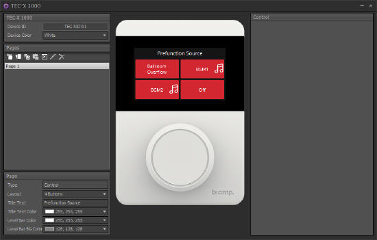
- Set the button Layout under Page. Depending on the model being used, up to 6 buttons can be configured on the TEC-X 1000 and 12 on the TEC-X 2000.
- Set default Title Text and Level Bar properties (even though the TEC-X 2000 doesn't have a level knob, it can control levels with buttons. If levels are being controlled, the level bar will be shown).
The design file is created with pre-programmed control for Ballroom and Pre-function areas. These may be edited as needed to fit design criteria and are included as a starting point of reference.
TEC-X-2000 TEC-X-1000
Biamp Canvas Software: An optional Biamp Canvas configuration layout has been provided for this application to be used as an additional point of control for the system integrator or operator. This is an optional part of the system, and is not required for the operation of the file. This Biamp Canvas layout is setup with basic controls for the system to allow for level adjustment, source selection, routing, and muting. It is created as a starting point and may be modified as needed to fit exact needs of the design application. The Canvas help file can be found here for reference.
Control System Integration: The example Tesira configuration file for this system design template has been setup to allow third-party control systems to easily control the Tesira system if desired. There are control points for Level, Mute, and Source Selection already in place to allow for you to use as it as-is, or add to as needed to suit the needs of the design. Control points within the file have been left at the default instance ID tag. These tags can be changed as needed to suit the programmer workflow or standardization.
Fire Alarm mute logic
In this application, we have added logic to control muting of the system on a contact closure from the fire alarm or other system. This logic is an optional feature of the file, and may be removed if not needed. This functionality is setup to work the same as the non-Dante version of this Ballroom file.
When connecting this fire alarm wiring to a Tesira system, it is important to know whether the switch is normally-open or normally-closed.
On a Tesira logic input, a short circuit will create a low logic signal (i.e., off), and an open circuit will create a high logic signal (i.e., on). Therefore, normally-closed mute switches create normally-low logic signals, and normally-open mute switches create normally-high logic signals.
Tesira logic blocks usually work best with normally-low logic signals. So, if you are working with normally-open switches, you'll usually need to either put the logic signal through a NOT gate, or just enable the Invert button in the Logic Input block.
It is important to note, it the shown configuration, the fire alarm mute will only mute the room and pre-function audio to allow audio from the fire alarm or evac system to be heard. The shown configuration does not have a path for an announcement from those systems to be played over the speakers. This functionality that may be added if needed with modifications to the file.
Further reading
- Tesira Network Infrastructure
- Gain Structure
- Loudspeaker Equalization
- General Audio Concepts
- TEC-X-2000 Landing Page
- TEC-X-1000 Landing Page
- Programming a TEC-X Control Pad to control a Tesira system
- Controlling a Source Selector with a TEC-X Control Pad
- Community D6 ceiling speaker
- Community V2-6 6" compact full-range speaker