Commissioning a Tesira Conference Room
This article describes an approach to manually setting up a conference system using Acoustic Echo Cancellation (AEC) technology in Biamp's Tesira products. It presents troubleshooting hints for some common issues that may arise during the commissioning of a conferencing system.
For many conference rooms the Biamp Launch automated room tuning system found in TesiraFORTÉ X and Devio SCX products, with Biamp Parle mics and amplifiers, will greatly speed up the installation process.
Each installation is unique, therefore each system will require unique settings and adjustments. Nevertheless, the following basic steps will provide good performance results for most typical AEC system installations. Remember that AEC provides echo cancelation for the far end participants in a conference. AEC does not resolve local echo (i.e., echo heard by the near-end participants) nor does it resolve acoustic feedback.
The process below details methods for achieving consistent conferencing mic gain structure, tips for routing the correct AEC reference signals, and notes on adjustments to optimize the ERL (Echo Return Loss) levels to get the best possible conferencing system performance.
This article also highlights the need to start with a good sounding room.
Electronic processing cannot make a bad sounding space sound better. As the saying goes, "You cannot make a silk purse from a sow's ear." If the intended use case for the room is as a conferencing tool, then the acoustics need to be considered in the design phase.
It is never easy to go back to the client and explain that a conference system which cannot be made to sound good is not broken or somehow faulty, but rather that poor performance issues are due to poor room acoustics.
It is possible to take acoustic measurements of a room and predict whether performance will be good or poor for conferencing. This allows the discussion of acoustic treatment options to happen prior to installation rather than during or after room commissioning.
The room: Noise floor, NC rating, and RT60
Arguably the single most important element in a conference system is the room itself. A noisy and/or reverberant room will generally sound awful for conferencing. A properly designed room with controlled reverberation and low noise floor will generally sound good for conferencing.
The importance of creating a controlled acoustic environment cannot be overstated. It is important to make the room as quiet as possible (low noise floor, measured as the Noise Criteria rating) and minimize reverberance (RT60) in preparation for installing the conferencing system. When properly applied, soundproofing and acoustic treatments will yield dramatic improvements in performance in most rooms.
There are basic prequalification site measurements that should be made to determine the basic acoustic properties of the room. Once these measurements have been made, you will have hard numbers that can be used to set performance benchmarks and clarify expectations for the results that the conferencing system may achieve.
An NC rating of less than NC-30 and an RT60 time under 0.5 seconds are typically considered suitable targets for conference applications.
Noise Floor
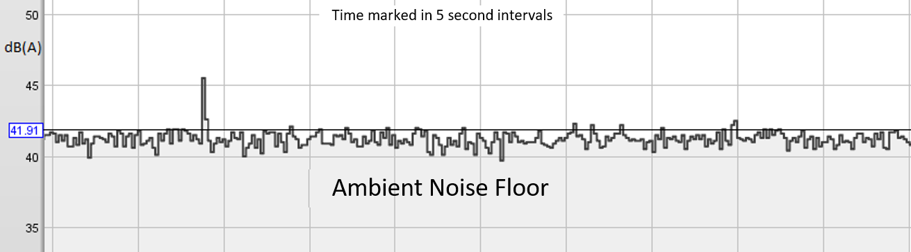 It is recommended to measure and document the ambient noise floor of the room (with the audio system off if it is already installed). The standard SPL measurement uses A-weighting and a slow response The noise floor will affect the results you can achieve with the conferencing system in terms of transmission clarity as well as intelligibility within the room. If there are mechanical noise concerns (noisy air vents, air-conditioner blower noise, exterior noise sources transmitted through windows, walls, doors, or other sources) they should be identified, documented, and mitigated if possible. If there are intermittent noises it is recommended to take measurements when these sources are active and inactive for comparison.
The difference between the measured noise floor and the level of the talker at the microphone is referred to as the signal-to-noise ratio. This ratio must be at least 10dB, but should be closer to 25dB for optimal speech intelligibility. An ambient noise floor of 35-40dB(A) or lower is considered appropriate for a conference room. This level corresponds with the Noise Criterion curve of 25-30.
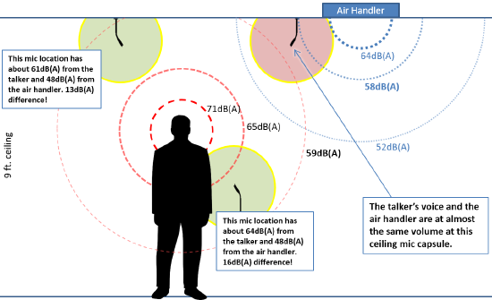 Take multiple noise measurements, both at the listener and mic locations, and compare results. A room measured at seat level may show a noise floor of 40dB(A), but a measurement made at the ceiling mic location, near an air handler, may show a noise floor of 65dB(A). In that case the 65db(A) noise floor is the most relevant data point since this is what the mic will "hear".
Noise floor measurements should be made at the noisiest locations. Some seats may have a noticeably higher noise floor versus others due to proximity to a nearby noise source. Be aware that a room that is relatively quiet at the desktop level may be much noisier at the ceiling mic locations.
In addition to the issue of noise created by air handlers or vents, air blowing around the mic capsule may result in unexpected air turbulence noises which can render a mic's output unusable. The use of wind screens may be necessary. Faux fur windscreens provide excellent mitigation of air movement noise and are available in many colors. Foam windscreens are more prone to noise as wind blowing across the surface texture of the open cell structure can still generate sound.
Noise Criterion (NC) rating
The Noise Criteria (NC) rating of a room compares the room's measured octave-band noise floor response curve against a standardized set of response curves to yield an NC-rating for the room. The NC-rating is a generalized method of explaining what applications a room may be suitable for, based on the noise profile.
RT60
 When commissioning a conference space it is recommended to measure the RT60 decay time of the space. An RT60 time of less than 0.5 sec is appropriate for most conferencing applications.
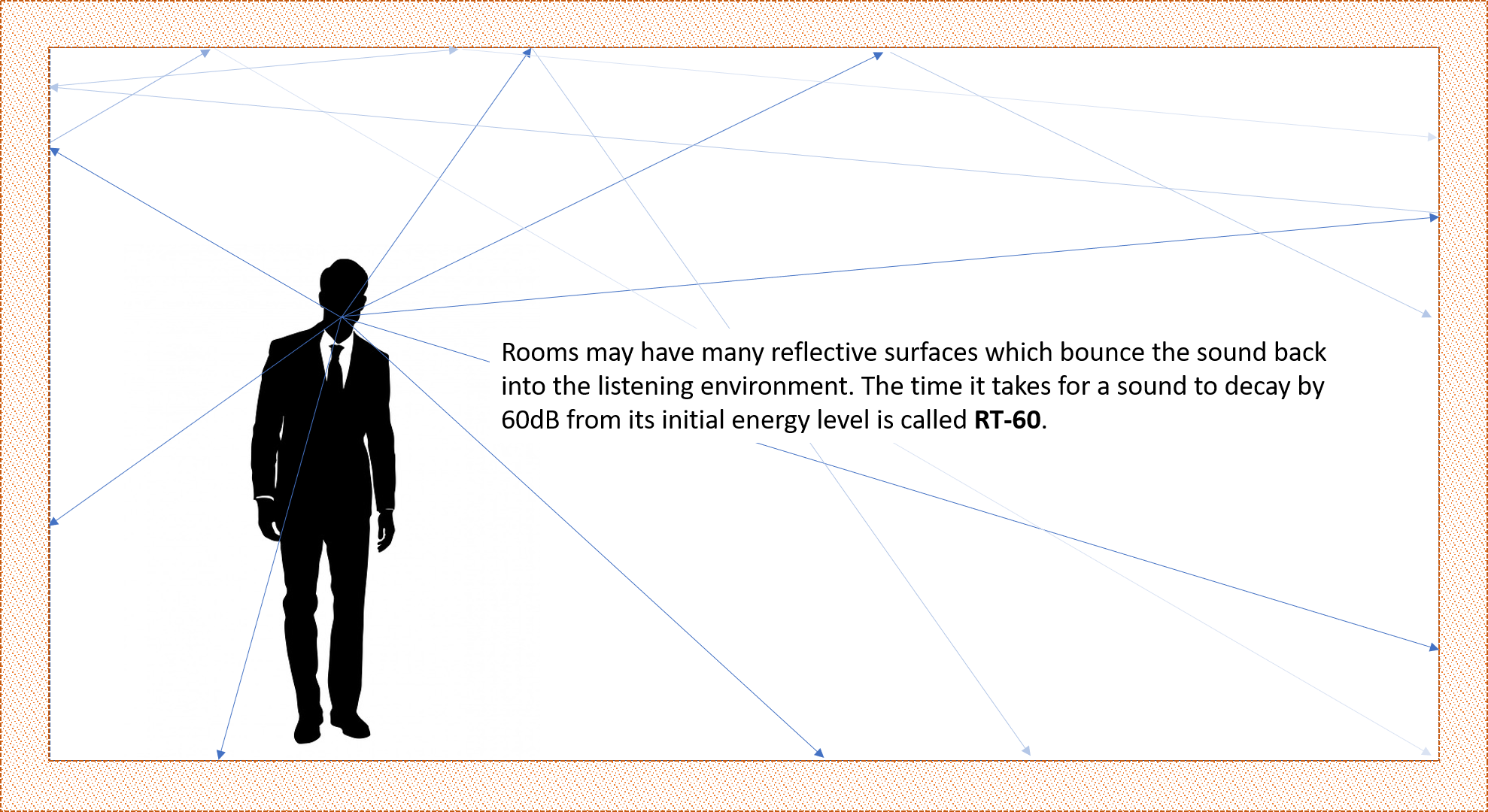
RT60 is a measurement of the time in seconds for acoustic energy to decay (decrease) by 60dB in a specified frequency range. Rooms with long RT60 times tend to sound bad for conferencing purposes (but may be wonderful for a pipe organ recital). High reverberance (long RT60) cannot be corrected with electronics. RT60 is reduced through physical modification of the space through the introduction of suitable acoustic treatments. The expense of the treatments can vary widely. There are many designer-friendly options available for use today, "acoustic treatment" does not mean "black foam eggcrate stapled to the walls."
RT60 times will vary at each mic location and can be averaged for an overall room value. It is important to note that certain locations may have more reflections and reverberance than others within the same room.
The effects of an overly reverberant room can also be mitigated with good (close) microphone placement to increase the ratio of direct sound captured vs. reverberant sound (direct-to-reverberant ratio). The combination of a reverberant space with distant microphones can be highly problematic.
A room that sounds bad in person will typically sound even worse at the far end of a conference call. Room acoustics are a mechanical property determined by construction materials and design and issues must be solved via mechanical means such as upgraded windows, quieter air vents, sound blocking construction materials, isolation hangars for drywall and ceiling tiles, acoustic treatments, bass traps, and other methods. The better a room sounds to begin with, the better your results will be when attempting to mic it.
Improving a room's performance
In designing a conference room for audio and video we are really creating a recording or broadcast studio environment, tucked into an office or education space. It is desirable to manage the room's acoustics with that in mind.
Noise Floor and NC rating
In a room with a high noise floor the fixes are typically mechanical in nature. High noise floor is caused by unwanted sound in the room, caused either by something in the room (HVAC vent airflow noise, computer or projector fan noise, refrigerator motors, etc.) or something external to the room (HVAC system noise, elevator motor noise, subway or highway traffic noise, airplane noise, outdoor wind noise, human speech or occupancy noise intruding into the space, etc.) Resolution to noise floor problems often involve working with other building specialists to find ways to reduce or eliminate the noise source or the path of acoustic intrusion.
The NC-rating of the room will improve when the noise floor is reduced. When a lower NC rating is required reducing the ambient noise in the room is the first item on the agenda.
RT60
In a room with excessive RT60 values a per octave analysis is critical. This will reveal what frequencies are most problematic and can inform choices of materials or products that will be needed to reduce the reverberance in the frequency ranges of interest. You want to focus resources on the frequencies which are troublesome to prevent putting a generic "sound deadening" or "acoustic treatment" solution in place only to find it missed the problem.
Rooms that have many hard reflective surfaces are notorious for high RT60 times. Parallel reflective surfaces make bad things even worse, allowing sound to flutter between them. An architectural acoustician can be called in to evaluate the room or solutions can be trialed to see if the desired results are obtained. For low frequency energy bass traps may be beneficial, for mid-range and high-frequency sounds acoustic panels of different thicknesses, heights, and widths may be needed. The thickness of the panel affects the frequency range it can be effective in, with lower frequencies requiring thicker panels to be effective. Acoustic diffusers are also useful, these act to passively disperse acoustic energy bouncing off them to minimize reflection hot spots.
Mics and speakers
Mic placement
The old real estate adage "location, location, location" also applies to mic placement.
For best results you want to position the mics as close to the talkers as possible. Ideally you will be able to provide one mic per talker. Having the mic close allows you to get the best signal-to-noise ratio (more spoken word and less ambient room noise) and the best direct-to-reverberant ratio.
As the distance between talker and mic increases, so does the apparent level of background noise relative to the spoken word. With increased distance from talker to the mic you will need to increase the input gain for the mic (amplifying the input from the capsule) to maintain the same apparent RMS value for the spoken content.
Mics are not able to differentiate between a squeaky chair, a barking dog, a noisy air vent, the CEO, or a fire truck. Mics will reproduce whatever sounds impact them. All sounds will be reproduced for the far end of the conference call to hear. The relative volume of each sound at the microphone is a function of the distance of the source to the mic, the amplitude of the sound source, the orientation of the mic's pickup pattern with respect to the source, and other factors.
Without being in the room with the talker, our ears and eyes lack the spatial and visual cues which normally allow our brains to filter out the distractions and focus on the important sounds. All noises are presented in relatively equal intensity and with apparent equal importance. Our ears (and our brains) get fatigued attempting to filter out or isolate the meaningful content.
Ceiling mics are typically the first choice for the interior decorator but may pose additional challenges for the audio integrator. It is critical to choose the right tool for the job. A cardioid-style microphone with the talker positioned on-axis with its pattern will outperform an omni-directional mic, or even the same directional mic pointed down in a "generic" position. In many cases, it is necessary to gently remind the client that the room is intended for collaboration and communication first so mics may need to be seen. Ceiling mics often have higher perceived ambient or background noise levels and poor signal-to-noise values relative to table-top mics due to the need for increased input gain, and tone may suffer due to the distance from the talker.
People have a tendancy to speak looking slightly downward and toward their notes rather than with chins held high and projecting toward the ceiling. A mic located 18 inches from the mouth of a presenter and 6 feet from the nearest air handler will sound better than a mic located 18 inches from an air handler and 6 feet from a presenter. Proximity to the desired audio source matters with microphones.
There are a number of online resources with recorded examples of lavalier, handheld, tabletop, and ceiling mics to allow direct comparison of the tone differences between them - it is highly recommended that you and your clients listen to the differences before committing to ceiling mics.
Tabletop mics positioned close to the talkers will provide a notable increase in performance over ceiling mics.
Speakers
In general, a room will sound better with greater tone and coverage control with a larger number of distributed small speakers at low volume rather than a small number of speakers at higher volumes. The small speakers should be arrayed to provide near-field reinforcement for the participants. Even more control over sound levels and feedback can be obtained if each speaker is wired independently to its own amplifier channel, or if groups of speakers are wired together in small zones.
Sample configuration file
A sample configuration with 3 partitions showing 3 different AEC applications (including mix-minus) can be found here:
Conference Room with AEC Sample File
Within Biamp's Tesira software, the AEC Reference (AEC Ref) can be configured as either a single channel reference or a per channel reference. The single channel reference block is the default.
-
The "single channel" AEC Reference option is used when the same content will be sent to all AEC References. Under the hood it is effectively a per-channel AEC Reference block with a hidden fan-out to the channels. (This option was added in the Tesira 3.1 release.)
-
The "single channel with pass-through" AEC Reference option is designed to be placed inline with the speaker output, just before the output block, so anything routed to the speakers will automatically be sent to the AEC reference. This is intended for rooms without local reinforcement of any mics. (You may optionally provide the AEC Ref signal via a discrete matrix output mirroring the output to the speakers. Any post-matrix level changes to the speakers should also be applied to the AEC Ref signal.) The output node of the single channel AEC Ref block must be terminated to either an output or a meter to allow the input path to compile.
-
The "per channel" AEC Reference is used when you need to provide unique reference sources for each mic. This will happen when you have a set of ceiling or tabletop mics that are not locally reinforced plus one or more locally reinforced microphones (presenter mics). It can also happen if you have a divisible space where some mics are in one room, and others in another, and thus the reference content is unique for each room. Any post-matrix level changes to the speakers should also be applied to the AEC Ref signals.
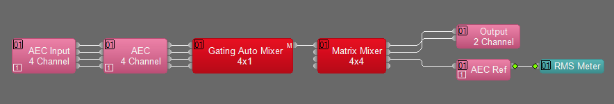
In most conferencing applications with multiple ceiling mics, a gating automixer can be beneficial to help in reducing ambient noise passed to the far end of the conversation. You can constrain the number of open mics allowed if desired, or allow the system to open any number of mics based on their signal level. The gating automixer should only be used for similar mics. If a room has 6 ceiling mics, a handheld mic, and a podium mic then the 6 ceiling mics would go to a 6-channel automixer and the other 2 mics would go directly to the matrix mixer. The difference in mic gain settings and noise floors of the mics may cause unpredictable gating behavior if you tried to add the podium and handheld mics to the automixer. Enabling the direct outputs on the gating automixer and connecting them to an RMS meter will allow you to easily monitor which mics are active at any given time.
Volume controls should be placed pre-matrix mixer for best performance. This allows the AEC Ref to properly follow speaker levels. As seen in the sample files this will allow user control over independent sources. The room master level is fixed. Users should have level controls only for things they can hear in the room. Users should not have control over transmit volume (which they cannot hear and which the far end is controlling via the receive level)
System calibration
We are assuming that the telephone (analog or VoIP) or video conference component is already operational. The proper sequence to setup is to ensure the amplifier and speakers are working properly, then verify microphone inputs and levels, and finally to adjust AEC settings.
Amplifier Gain Structure
-
NOTE: For proper documentation of room coverage it may be required that you use pink noise as a source and measure to a pre-specified level of audio reinforcement.
-
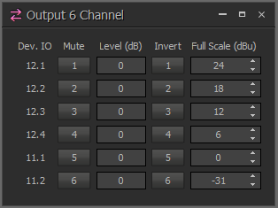
Check the spec sheet for the amplifier and find the "input sensitivity" rating. It specifies the input voltage which will produce the maximum rated output power without clipping. This value is needed to set the correct full scale output voltage (dBu) value in the Tesira output block. You need to match the output voltage from the Tesira to the input sensitivity of the amplifier. The Tesira is capable of 12.23v output at the 24dBu setting; if the amplifier is expecting to see 0.775v at the input then the input may clip if the Tesira setting is not modified. It will also be difficult or impossible to get proper gain staging through the Tesira. See our articles on gain for further information.
- If the amplifier's spec sheet is for some reason unavailable to you, it is possible to rough-in level calibration between processor and amplifier:
- Turn the amplifier down. Within Tesira software set pink noise as a source playing at 0dBu. Do not attenuate it before the amp. Slowly turn up the amplifier, if it cannot be brought up to full output without clipping go back to Tesira software and reduce the Full Scale (dBu) Output in the Output block until you can bring the amps up to full output with an SPL level of 80dB(A) in the room. The meters on the amps should fairly closely resemble the meters in Tesira. It may be that the amps are under- or over-powered for the room, if so it may be necessary to apply further gain adjustments at this point but this process will get you in the ballpark.
- With suitable spoken word program material playing from a recording (spoken word at approximately 0dB RMS on input meters and not attenuated through the Tesira DSP layout) you should have sufficient audio level (about 76dB(A)) in the space. Spoken word program levels should be playing out at approximately the same volume as conversational speech in the room. This is about 70dB(A) at the listening position. Setting the amps to allow extra headroom up to 76dB(A) will allow users to tailor the level to their needs.
Mic levels
-
If using Biamp's Parle microphones be sure to add the Parle processing block from the controls menu in Tesira.
-
With an assistant seated or standing in suitable locations (as appropriate to mimic the use of the room) adjust your microphone input gains (within the "AEC Input" block) such that your RMS meters are hitting approximately 0dBu when they are talking. If you are using ceiling mics, this level may not be achievable.
-
An input gain setting of 42 to 54 dB is typical for analog ceiling mics. An input gain setting of 30 to 48 dB is typical for analog tabletop mics.
-
To ensure consistent calibration results you can use pre-recorded vocal samples played through a speaker placed at the talker position. Pink noise can also be used as a noise source but it is recommended that you wear hearing protection if it will be active for more than a few minutes at a time. Set the volume so the slow A-weighted SPL level measured at 1 foot from the speaker is between 68dB-A and 71dB-A. The loudspeaker should face the microphone being tuned, and should be placed at the same distance from the mic as the intended human talker. (Installed room speakers should not be used as the source.)
-
To set the EQ and other settings of your mics properly you will need to be able to listen to the mics in isolation. Isolation can easily be achieved by calling into the room from another room onsite or another offsite location. For tuning purposes it is best to be able to listen on headphones while in a quiet space so you can hear the nuances of changes being made in the system. You will also want to be able to remotely control the system from your listening location so you can adjust gain, EQ, and other settings. Remote control can be done via either a remote login session with a computer connected to the system, via a WiFi connection to the control network, or by simply stringing a long CAT-5 cable between rooms to allow a data connection while getting sufficient acoustic isolation from the room so you can listen critically.
AEC settings
Double-click on the "AEC" processing block to see the per channel controls. AEC settings will need to be applied for each mic.
-
AEC should be enabled for all microphones, but not for any other input source (the "AEC" indicator will be blue when active). Echo is eliminated from the mic by comparing any signal routed to the AEC Ref with the input signal of the mic and cancelling out anything the two signals have in common. Anything which is routed to the local speakers should go to the AEC Ref at the same level (except for the mic itself, if local mic reinforcement is being done).
-
Do a test call and listen to the mics. For testing it may help to mute all mics (within the AEC block) so you can then listen to one mic at a time in isolation. Unmute mics one at a time for adjustments.
-
The NLP Level is the non-linear AEC processing component. It provides adaptive filtering to reduce late reflection energy which arrive at the mic outside of the time window of the AEC algorithm. Settings are None, Low, Medium, and High; where Low is a shorter time window and less aggressive filter and High is a longer time window and more aggressive filter. To tune this you will need to be the far end participant on a call. Start with this feature disabled and test the settings from Low to High while listening to a talker in the room. Late arrival energy may sound like a short "bark" (try Low) or a partial to full late echo of a word (likely to need High, or lower input gain on the mic). Words ending with plosives such as "check" will produce a clearer echo than soft words such as "fish".
-
Within the "Ch Processing" settings go to the "Advanced Filters" tab. The High Pass Filter (HPF) should be adjusted to remove low frequency "rumble" from the mic input. Most applications are fine with values below 150Hz, however, in some rooms values into the low to mid 200's are needed. At higher frequencies (150Hz and up) this will attenuate lower-frequency spoken word tones as well as noise and may be a point of concern. It is generally found that it is less fatiguing to hear a voice which is slightly "thinner" or which has less "body" than to hear persistent low frequency noise. In difficult cases it is left to the installer to determine the best tradeoff between the two. The High Pass Filter is applied before Echo Cancelation and before Noise Reduction in the signal path so it will prove beneficial to both. (Note that the HPF within the AEC processing block is preferred to a standalone HPF applied post-AEC processing. The embedded HPF will remove low frequency noise from the input signal before it reaches the noise reduction and AEC algorithms, resulting in the algorithms focusing on the spoken word content frequency range rather than the sub-sonic content.)
-
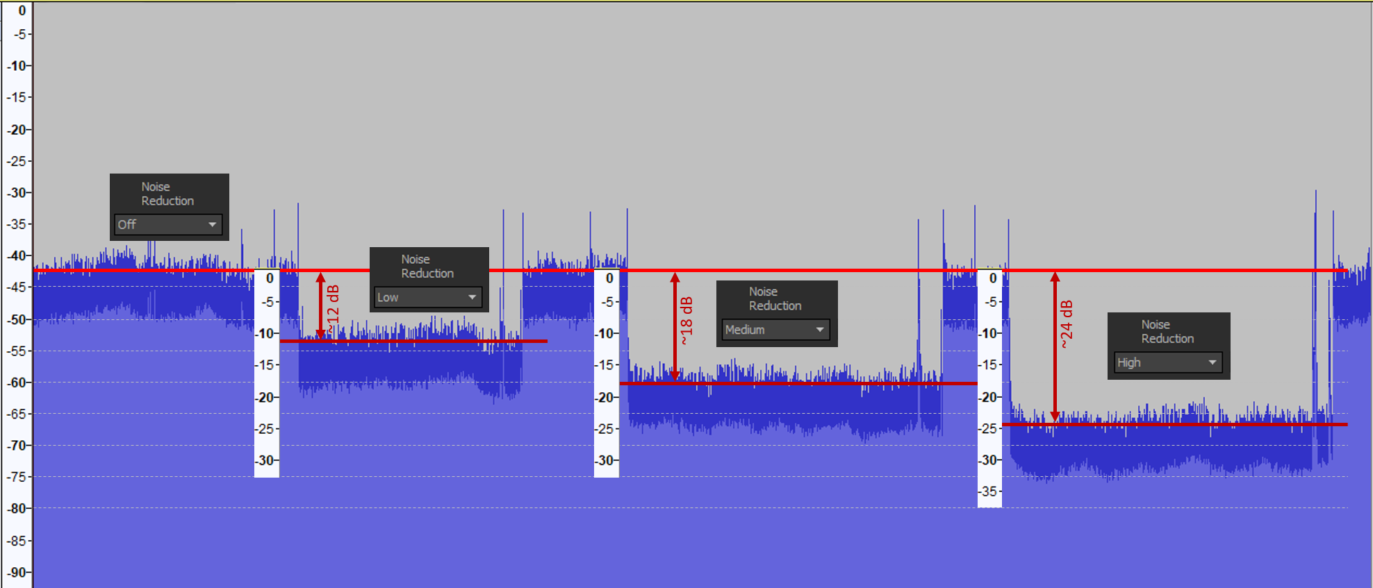
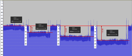 Now is the time to begin applying Noise Reduction (NR). Start with Low and see how it sounds, then move to Medium. If you need to use High be aware that it is very sensitive to the input gain level. If the input gain is too high you will hear artifacts of the noise reduction which typically are described as dripping or running water. Reduce the input gain until the artifacts disappear. The artifacts are a residual effect of an artificially high noise floor.
 -
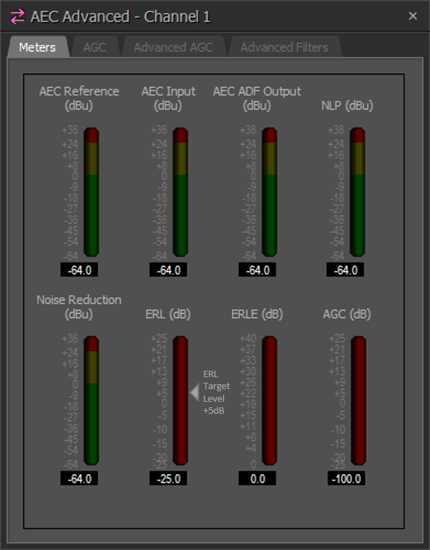
Check the Echo Return Loss (ERL) value in the Ch Processing parameters of each AEC input. For best performance results in Tesira, ERL (dB) value should be between 0 and +15dB while the far end talks. A value between +5 to +10 is ideal. This indicates the total amount of difference between the signal sent the AEC Reference and what is heard at the AEC processing block.
-
Repeat the prior 4 steps as needed for each mic.
-
Unmute all mics.
-
Adjust your gating automixer to allow the desired number of open mics (NOM). For many conferencing applications this can be left undefined (the mixer will open channels based on their signal level). In noisy environments it may be desirable to limit the number of open mics to better manage the noise to the far end. Enabling the direct outputs on the gating automixer and connecting them to an RMS meter will allow you to monitor which mics are active at any given time. The mix output should be sent to the far end.
-
Once operational, allow users to make level changes with the Tesira level controls but do not change the volume of the amplifier itself. Level changes at the amplifier will upset your ERL calibration.
Cue output
When tuning any room for conferencing, it is important to know what is being sent to the far end. It can be helpful to set up a local output to assess changes made to microphone settings. This output can simply be one of the analog outputs of a Tesira with an adapter wired to headphones, or the USB output of a Forte or EX-UBT connected to a PC for headphone monitoring and recording samples of the audio. 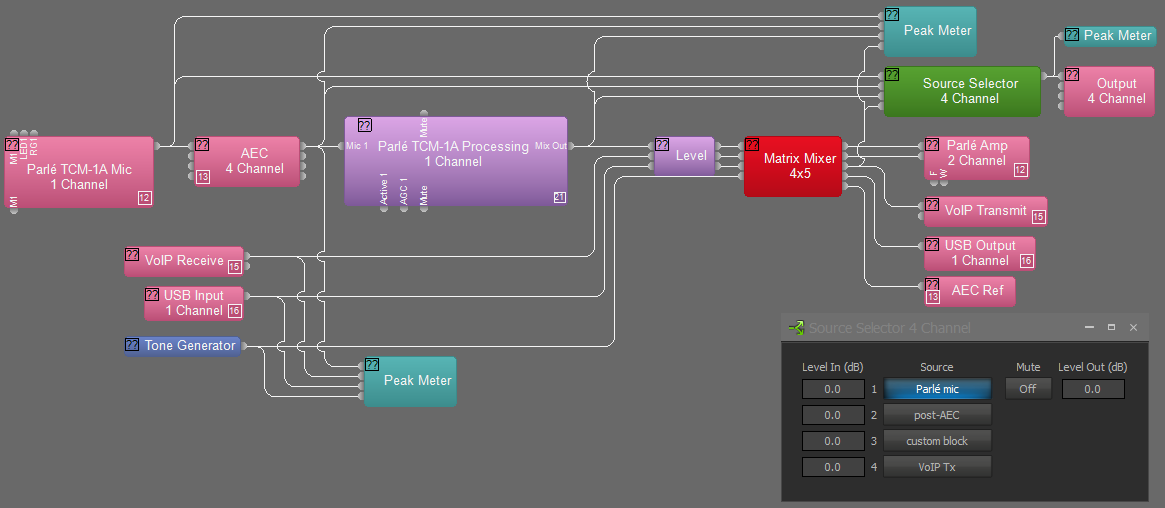
A Source Selector block with 4 or more inputs can be added to the layout. Connect the first input to the output of the Parlé microphone block (this is the raw output of the microphone array). Connect input 2 to the output of the AEC processing block (this reveals changes due to the AEC echo reduction, noise reduction, and high pass filter). Input 3 should be connected to the output of the Parlé custom library processing block (this contains a level boost, EQ curve, Gating Automixer, and AGC). If additional processing objects are added, then additional inputs should be defined for the Source Selector to incorporate these in the testing. The last input should be taken just prior to the transmit block (whether it is VoIP, POTS, USB, or analog out).
Wire the Source Selector to the appropriate output and update your hardware. Put on headphones and you should be able to choose the pick points in the mic signal chain where you'd like to compare performance. This allows the local technician an opportunity to tune the mic performance without hearing any effects of codecs on the signal. Once the local performance is verified then you can place a call and assess the transmit quality on the far end.
The cue output can be placed inline with the transmit output path so the far end listener can hear each selection pick point. In systems with USB connections it can be connected to the USB output for VTC far end or for recording to a PC. It can also feed an analog output to connect to a set of headphones to listen locally.
Test calls
Calling into the system from a remote location (from the room next door, a cell phone in the hallway, or having a co-worker call from your office) will allow you to determine if there is any echo at the "far end" of the call.
Being remotely connected to the Tesira software controlling the network while calling into the room will allow you to discover echo issues and refine ERL levels in the system while speaking through the room system. The remote connection can be accomplished with a second computer using remote desktop connection software, or locally onsite with a connection from your laptop to the Tesira control network (wired or via wifi, although it is not recommended to push configuration updates over wifi).
Occasionally there will be issues with audio loops causing echo when video conference systems are present, please refer to our articles on VTC troubleshooting for assistance.
Speech Transmission Index (STI)
As a final step in validating a room's performance the Speech Transmission Index (STI) rating should be measured and recorded. STI defines how difficult it may be to understand speech through an installed sound system in a given environment.
The measurement of the Speech Transmission Index (STI) rating uses an industry standard test signal to measure how sound played through loudspeakers interacting with the room’s natural acoustic response affects intelligibility. The interaction is captured in a metric described on a scale of 0 = bad, to 1 = excellent.
A low STI score will indicate it is difficult to understand speech in the space, typically this may be due to high ambient noise levels, excessively long RT-60 times, intrusive or competing sounds, inadequate sound pressure levels from the speakers, poor quality speakers or defective speaker installations not properly reproducing the desired audio in the listening area.
A high STI rating indicates that the space is well suited for understanding speech content at the target volume.
Troubleshooting AEC systems
The following simple troubleshooting techniques should be used as needed.
Objects in the AEC path won't compile / file won't compile
-
This can occur if the user selects the "single channel with pass-through" reference mode rather than the "single channel" or "per channel reference" mode when adding the AEC inputs. An endpoint is needed for the signal path to compile. Confirm that the single channel with pass-through AEC Ref block has something connected to its output node, either a path to an output or a meter.

Residual echo is heard
-
Verify that all AEC Reference input nodes are connected, even those that are not being used.
-
Verify that routing to the AEC Reference is correct - any source routed to the speakers should be routed to the AEC Reference as well. In general, microphone signals are not usually sent to the AEC Reference (but in some cases it can be beneficial). A microphone signal should never be sent to its own AEC Reference channel under any circumstances.
-
Meter the signal feeding the AEC Reference and make sure it is within the recommended range (-3dBu to +3dBu).
-
Adjust NLP Level settings to reflect your use case. This is the Non-Linear Processing (NLP) circuit. "None" equates to bypassing the mode, "High" has the longest window and may help in very reverberant spaces. The setting is related to the total (round-trip) delay the far end experiences.
-
Consider additional acoustic treatment for the space.
-
If a persistent echo is present try muting non-microphone inputs one by one and see if the echo stops. The transmit audio may be getting returned back with the receive audio.
-
If the channel order of the AEC input cards has been manually allocated (fixed in unit set to true, and channels reallocated), contact Biamp Support for assistance with the routing to the AEC Reference.
ERL values out of optimal target range
ERL (Echo Return Loss) shows the difference in level between program material arriving at the AEC reference and those same program material arriving at the AEC input after having been introduced into a physical space and picked up by the microphone.
-
A positive value indicates the signal at the AEC Ref is higher than the signal being received at the input of the AEC processing block.
-
A negative value means that the signal at the AEC Ref is lower than the signal being received at the input of the AEC processing block.
ERL value greater than +10dB
If the ERL value is too high, there is an unusually low level of acoustic coupling between the microphone and the speaker. Possible causes may be:
-
Tesira output gain (dBu) is not correctly matched to the amplifier's input gain.
-
Input gain of the microphone is unusually low.
-
Too much level being sent to the AEC reference.
-
Gain structure is not optimized.
-
Poor microphone / speaker placement.
ERL value lower than 0dB
This symptom would be indicative of too little source material being seen in the AEC Ref relative to what is being captured at the mic.
-
Confirm signal routing for the AEC path.
-
Confirm you are in a call state which sends program material to the AEC reference.
-
Check mic input gain.
The mics sound garbled or like they're "underwater"
-
Check that the mics are not routed to their own reference. A mic should never be sent to its own AEC reference channel.
-
If a persistent echo is present, try muting non-microphone inputs one by one and see if the echo stops. The transmit audio may be getting returned back with the receive audio.
There are audible artifacts when Noise Reduction is on "High"
-
The mic input gain is too high, lower the input gain setting until digital artifacts go away.
-
If the noise floor is too high there will be audible artifacts as the noise reduction attempts to cancel as much as possible. Reducing the noise floor to reasonable level allows the NR to remove noise and pass the desired content through. Once the digital artifacts are gone you can boost the mic signal later in the signal path using a level control or other DSP object.
-
The Low setting is equal to approximately 6dB of noise reduction, the Medium setting is about 15dB of noise reduction, the High setting is about 22dB of noise reduction. At the high setting the chance of digital artifacts is greatest due to the extreme noise cancelation in place, care will need to be taken to provide proper gain into the noise reduction circuit.
Automatic gating is not functioning properly
-
If you are using a gating auto-mixer and it is not reacting as expected you may need to confirm your input levels are adequate to trigger the gates. If it is not functioning properly it indicates that the Adaptive Threshold Sensing (ATS) is not working properly. Make sure that all microphone inputs have sufficient gain applied to achieve a nominal 0dBu RMS level when talking into the microphone.
-
The default Automatic Gain Control (AGC) values may need to be modified for your application - they are modified in the Ch Processing > AGC tab (or in the AEC block Properties > DSP Properties).