Hospital paging and evacuation
This system design template shows how Vocia products can be used to easily create a facility-wide paging and evacuation system for healthcare environments. Vocia is a highly reliable solution that provides excellent audio quality while managing all your paging, background music, and emergency communication requirements. It is powerful, scalable, and flexible, and can meet a facility’s needs well into the future. A decentralized approach, which places digital signal processing in all of the endpoints, creates a solution with no single point of failure, and provides a means to expand an existing system as needs grow.
Overall, the healthcare vertical market has an extended demand on system availability and security measures, especially when it comes to hospitals with hundreds of patient rooms. Vocia is capable of meeting and exceeding these requirements.
System description
The outlined Vocia system was designed to provide a building-wide distribution of critical evacuation messages,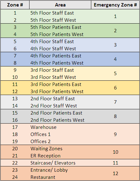 regular paging functionality and playback of background music in public areas.
- The table on the right shows a breakdown of all available zones in the building
- The total amount of speaker circuits / zones in this example facility is 24
- Most publicly accessible areas are located in the 1st floor
- All nursing staff and patient rooms are located on floors 2nd - 5th
- The upper floors divide in an east wing and a west wing, of which each is a separate hospital ward of its own, with patient rooms and separate staff areas
The objective of the speaker system is not only to provide a high level of security in case of an evacuation, but to also allow for a smart and granular zone assignment to make directed announcements into public areas, staff areas and patient rooms. While the patient rooms shall remain undisturbed most of the time, no important information should miss its recipient throughout the entire building.
Emergency functionality
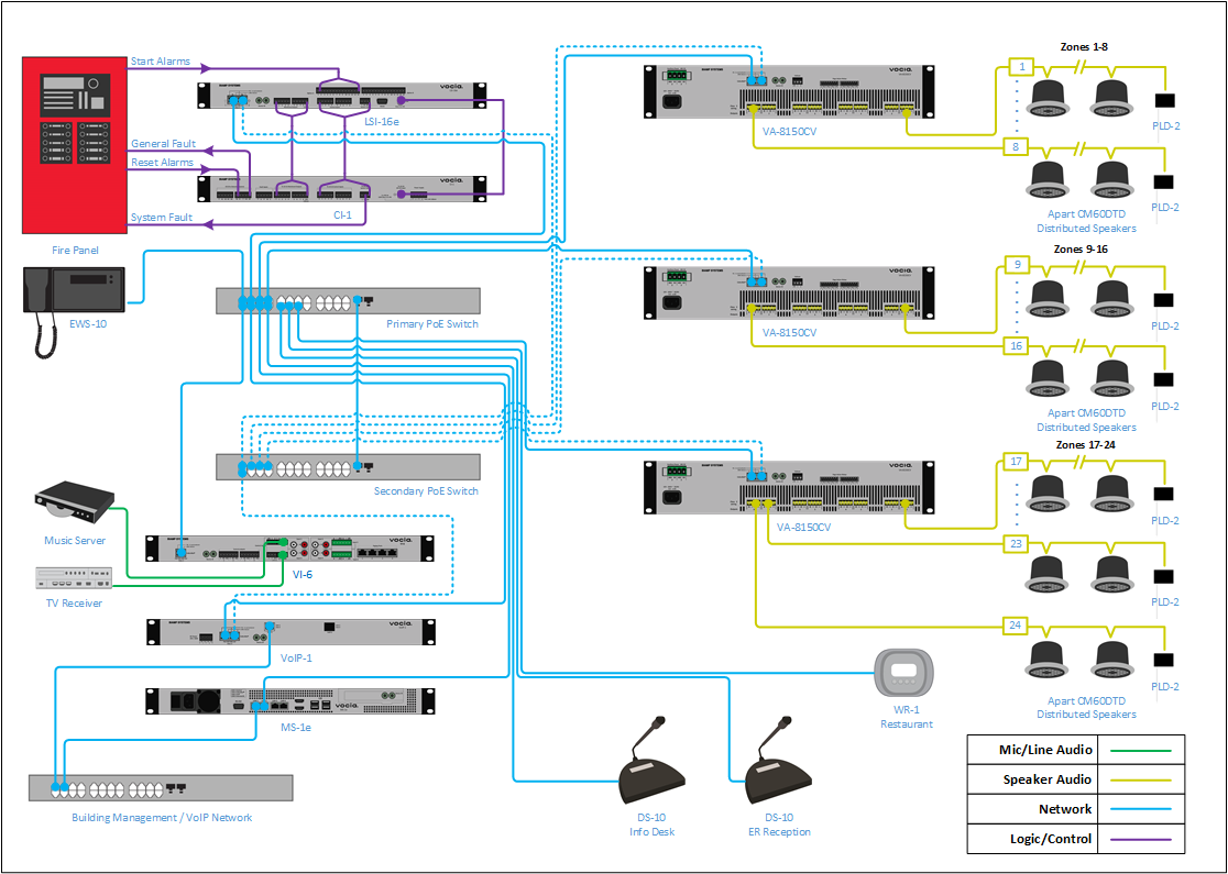
The fire panel shall be connected with Vocia's Life Safety Interface (LSI-16e) to trigger evacuation messages in case of an emergency. In order to maintain an effective and organized method of assisting patients and personnel to evacuate, the fire panel has granular access to single evacuation zones. This allows evacuation of single floors and areas in which a fire has been detected, without unnecessarily alarming unaffected areas.
In this template, a default alarm tone (500Hz) is used for the Vocia configuration as a placeholder. It might be replaced through a professionally recorded announcement to help people safely evacuating all public areas. It could also be a coded message (e.g. "Dr. Smith, code blue.") to instruct all personnel performing the necessary actions without worrying patients who are requiring assistance. Vocia allows the assignment of individual emergency messages for different emergency zones, if applicable.
An emergency paging station is located nearby the fire panel to give authorities and first responders the ability of a high priority page throughout the entire building or into individual floors of the building. Any announcement made through the EWS-10 paging station will surpass the priority of ongoing announcements or emergency messages.
Please note that local standards may apply to determine the design, commissioning and operation of voice evacuation and fire alarm systems. System configuration, connection methods and sound pressure levels stated in this system design template are exemplary only, and must be revised by authorities before being applied.
Paging functionality
The system shall be able to allow live and delayed paging into single or combined zones of the facility. This will be either possible through any of the paging stations (Info desk and ER reception) or through a telephone paging function accessible for all medical personnel. A delayed paging feature allows the user to record an all-call announcement and be able to delete it if desired, before it is played back throughout the entire facility.
Background music
There are two audio sources connected to Vocia VI-6: A background music program provided by a music server, and the audio feed of a satellite receiver, providing the TV program for the restaurant. While most zones are set up fixed to one source or another, the restaurant staff will be able to switch between the two sources and also control the volume if necessary.
Equipment list
- 3x VA-8150CV Amplifier
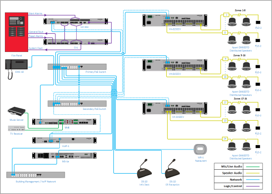
- 24x PLD-2 Passive Line-monitoring Device
- 1x LSI-16e Life Safety Interface (includes IM-1)
- 1x CI-1 Control Interface
- 1x MS-1e Message Processor
- 1x VOIP-1-2 VoIP Interface
- 1x VI-6 BGM Input
- 2x DS-10 Desk Station
- 1x EWS-10 Emergency Wall Station
- 1x WR-1 Wall Remote
- 2x Managed Ethernet Switch, PoE (902.1af, Class 3) capable
- Apart CM60DTD 6.5" two-way, thin edge ceiling loudspeaker, with back can (Quantities as needed to meet project scope)
Vocia configuration file
A complete Vocia configuration file is available for download here:
Hospital paging and evacuation - 24 zones.vop
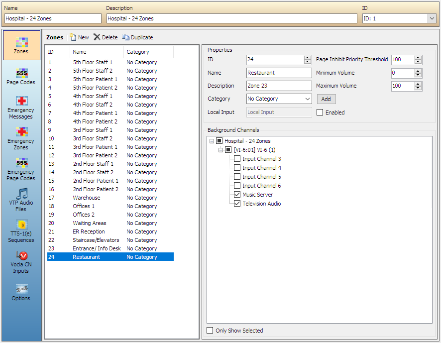
It already contains the necessary settings to get the system into an operational state. The Vocia software must be installed to open and review the configuration file. In order to provide a better understanding on the most essential settings inside the software, the Zones and Page Code assignment can be previewed below.
| Zones Configuration | Pages Codes | Emergency Zones | Emergency Page Codes |
 |
 |
 |
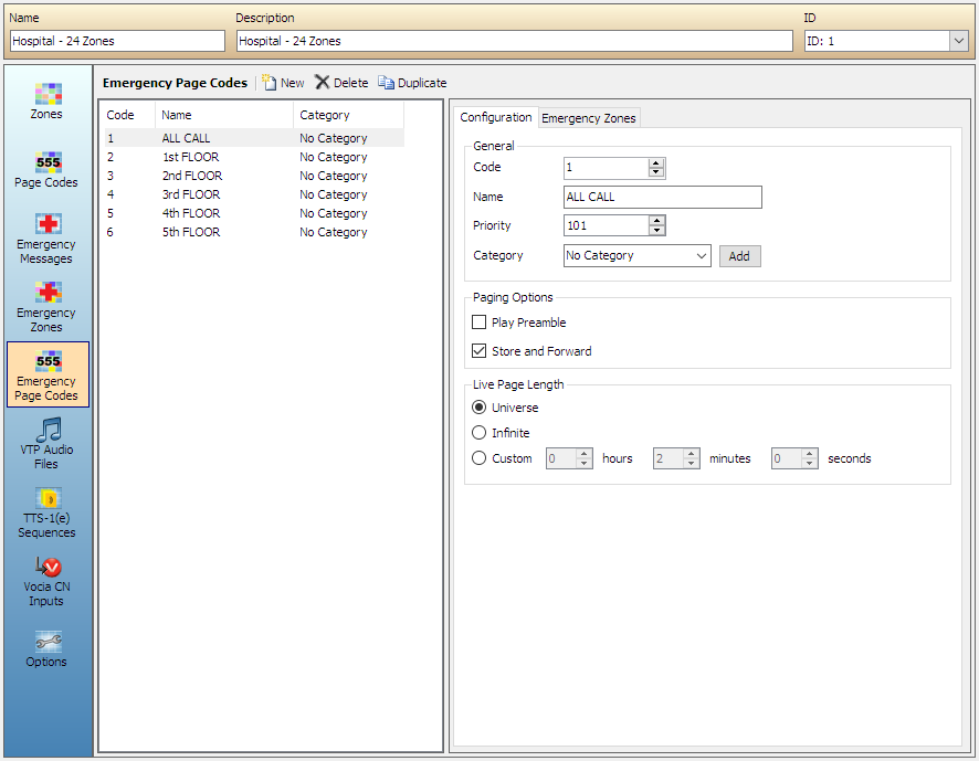 |
- All 24 Zones reflect the actual speaker circuits as listed at the beginning of this document
- Page Codes are Zones divided into logical groups to improve usability. All Page Codes use 3-digit numbers, while the first digit reflects the floor level of the building.
- The 12 Emergency Zones typically combine two or more single Zones. Refer to the table at the beginning of this document
- Emergency Page Codes are Emergency Zones divided into logical groups to improve usability. All Emergency Page Codes use 3-digit numbers, while the first digit reflects the floor level of the building
External connections to the system
Fire panel connection to the LSI-16e
The functionality of the LSI-16e has been tailored to the specific requirements in the EN 54-16 European life safety standard. However, the LSI-16e and CI-1 are still applicable in installations that require highly reliable and fault-tolerant systems with voice evacuation functionality, even if there is no need to meet EN 54-16 standards. Some notifications are specific to EN 54-16, for example, General Fault, General Alarm, Protection Fault, etc and may not be applicable for your jurisdiction. More information on Alarms and Faults can be found here. In this application using the CI-1 facilitates connectivity to the Fire/Evacuation Detection System (CIE) allowing bi-directional control and monitoring. Extra contact closure inputs on the LSI-16e are being used for severe weather emergencies.
Setup requirements:
- Links between LSI-16e Life Safety Interface and CI-1 Control Interface with supplied jumpers. A detailed setup guide can be found here
- 24v Standard Compliant external power supply to the CI-1
- Alarm triggers from CIE to input channels 1 - 12 on the LSI-16e general purpose inputs - Places the Vocia System in Emergency Mode according to the configuration
- Alarm Reset link from CIE to Rs terminal on the CI-1 - Resets the Emergency Mode in the Vocia System
- System Fault link between LSI-16e and Fire Panel. Allows fire panel to alert when the Vocia Evacuation System has a System Fault and requires attention
- Voice Alarm Active link from VA terminal on the CI-1 to CIE - Signals the CIE that Vocia has an active alarm
- General Fault link from the GF terminal on the CI-1 to CIE - Signals the CIE when there's a fault in the Vocia System
Optional:
- Alarm Silence link from CIE to Si terminal on the CI-1 - Silences the alarm in the Vocia System
Required physical connections general purpose inputs: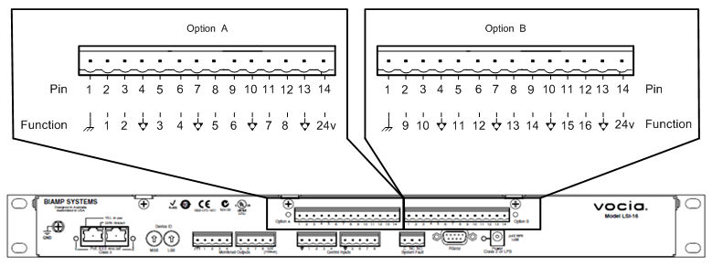
- Inputs are configured as "High-Range monitored"
- Loss of individual connections will be indicated as a General Fault (GF)
- General purpose inputs are divided by chassis and logic ground (GND) connection pins. Note this will require connecting the physical inputs 1 through 14 (Option A) and 1 through 6 (Option B) to trigger the emergency zones 1 - 12 please refer to the picture on the right or review the full LSI-16 connection documentation here
VoIP integration
The VOIP-1 telephone paging interface provides a dedicated network port which connects the the local VoIP network. The telephony system must be configured to provide at least one extension for dedicated telephone paging use. The VoIP system must support 3rd party SIP endpoints in order to successfully register the Vocia VOIP-1 with the VoIP registrar server.
For more information on tested VoIP telephone systems and compatibility with the Vocia VOIP-1, please refer to the compatibility matrix available here.
It this system design template, calling the dedicated extension number will make the VOIP-1 answer the call with a short welcome announcement. The caller has now four paging options to select between. The selection can be done by DTMF dialing the following IDs with the phone:
- 100 - All Call
- 103 - All Visitor Areas
- 104 - All Staff Areas
- 999 - Emergency All Call
More paging options can be added as necessary. If it is required to allow for multiple users paging at the same time, the VOIP-1 supports up to four VoIP lines which can be used simultaneously. For an even higher demand of simultaneous VoIP pages, the MS-1e supports up two 20 incoming connections as a SIP trunk. More information available in the further reading section.
Speaker lines
- Speaker circuits are being installed as constant voltage speaker lines, 70V or 100V can be selected via software
- The total power of parallel-connected speakers should not exceed 150W per channel
- Select speaker transformer taps individually to allow for the emergency messages to be at least 10dB SPL above the A-weighted noise floor in each area. Note that in quiet areas, like a hospital ward, the speaker may provide enough SPL even at the lowest tapping
- Attach a PLD-2 device at every last speaker of each individual speaker line. The conductors of the PLD-2 will be connected in parallel to the speaker like, as it was a speaker itself, and allows the amplifier to monitor the speaker line from end to end. An interrupted speaker line will result in an Audio Path Fault message at the LSI-16e
- If the actual installation conditions require speaker line branches, an active End-of-Line Device (ELD-1) must be used instead the PLD-2. There can be up to 15 ELD-1 per speaker line to accommodate for branch connections. Note that the ELD-1 requires a PoE-enabled connection to the Vocia Network
Control network
- The control network port (LAN 1) of the MS-1e can be connected to a building-wide network
- A free static IP address for the MS-1e should be determined with the IT manager
- If desired, a connection to an Email Server can be set-up to enable notifications in case of unusual system events
Networking details
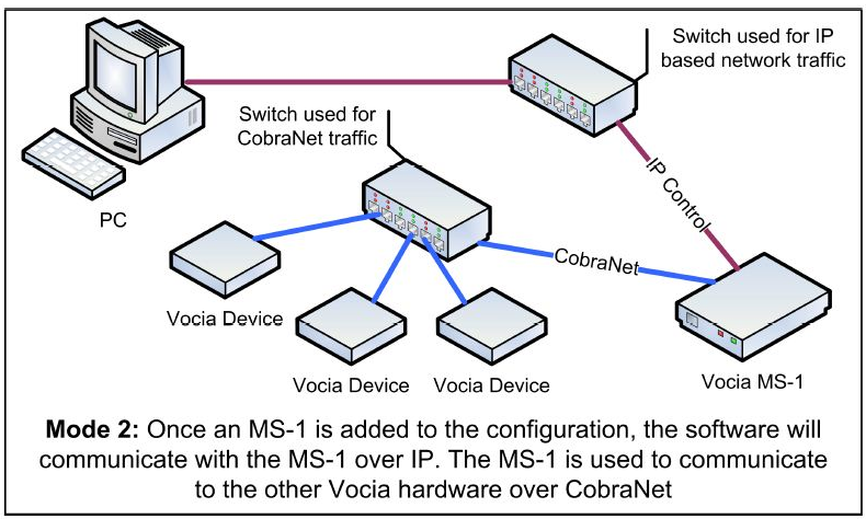 Vocia supports two modes of network communication depending on the network topology. One requires a direct connection to a CobraNet network while the other requires an IP-based connection to the MS-1e Message Processor to access the system. Since this system does include an MS-1e, the second method will be used. The factory default IP address for the MS-1e is 192.168.1.101, which is already set up in the example configuration accordingly. Should any problems occur to connect to the system, use the MS-1e device maintenance tool in Vocia Software.
Setup Requirements:
The following devices will require 802.3af (Class 3) power from a PoE capable switch or a suitable PoE injector:
- 1x LSI-16e Life Safety Interface (2 Ports)
- 1x VOIP-1-2 VoIP Interface (2 Ports)
- 1x VI-6 BGM Input
- 2x DS-10 Desk Station
- 1x EWS-10 Emergency Wall Station
- 1x WR-1 Wall Remote
System setup
All Vocia devices are set, by default, to unity gain. This allows the system to start working, once the file is loaded, with minimal adjustments.
- Select output voltage on the VA-8150CV amplifier to 70V or 100V as needed
- Adjust amplifier output level as needed for each zone
- While at the amplifier's properties, go to "ELD Assignment" tab and select "Recalibrate All" to calibrate all PLD-2 modules
- Check and confirm adequate DS-10 microphone input level from the Audio & Live Control tab found under DS-10 properties
- Connect music sources to VI-6 and verify levels under the VI-6 Audio and Live Control found under VI-6 properties
- Set background source for a zone
- Verify there are no Alarms or Faults active in the LSI-16e. If present, verify wiring and terminations
- Test the Emergency Evacuation Systems with each of the triggers for proper functionality and validation