Medium House of Worship
This system design template shows how Tesira SERVER products can be used in a medium-sized House of Worship installation. The system is designed to give users the option of whether to control it primarily from the Tesira SERVER or from an attached mixing console.
The primary system will consist of microphone inputs at the pulpit and lectern for speech reinforcement throughout the sanctuary. There will also be microphone inputs for musical instruments and choir vocals, as well as reinforcement of the congregation. In this system, volume levels may be controlled from a Dante-enabled mixer board or from TEC-1 devices located in the Sanctuary and at the Sound Board. Automixers have been included so that use of the Dante Mixer is not necessary if the space is being rented by those unfamiliar with using a mixer board. An additional TEC-1 is positioned in the lobby to allow for zone control in that area.
Room design
Medium House of Worship Functionality Scope: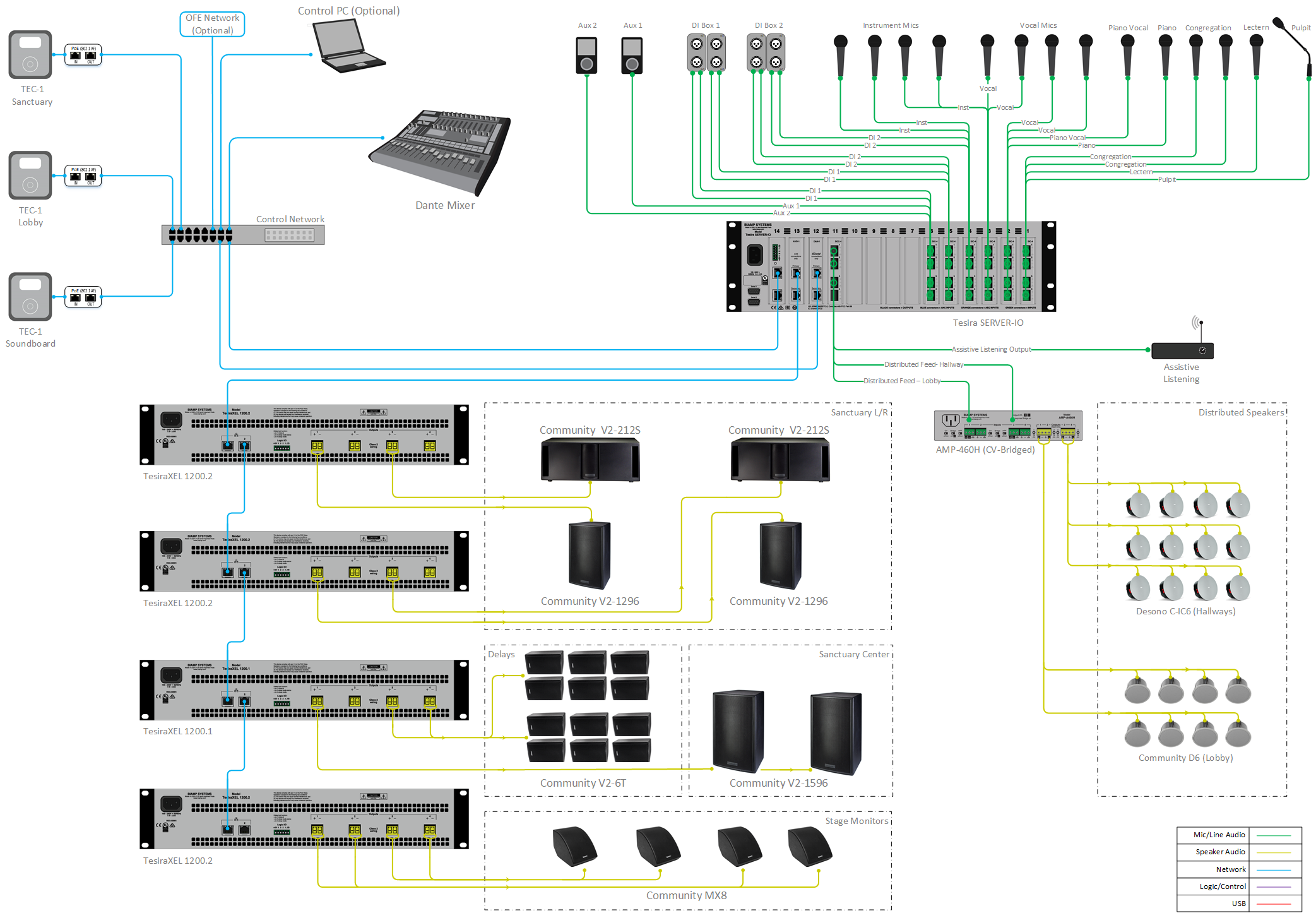
- Automixed Pulpit, Lectern, and Altar microphone inputs with master level adjustment.
- Automixed Vocal microphone inputs with master level adjustment.
- Piano, congregation and musical instrument microphone inputs with individual level adjustment per channel.
- Ability to enable/disable Dante Mixer.
- Ability to enable automixed mode so space can be rented out to people without knowledge of using Dante Mixer.
- 70V distributed ceiling speaker feed for Lobby and Hallway areas.
- Distributed feeds to Sanctuary main cluster speakers.
- Distributed 70V feeds to Sanctuary back speakers with the ability to adjust delay.
- Feeds for stage monitor speakers.
- Feed to Assistive Listening System.
- TEC-1 mounted in sound booth area provides volume level and routing controls.
- TEC-1 mounted in Sanctuary provides volume level controls.
- TEC-1 mounted in Lobby area provides zone volume level controls.
Equipment list
Below is the list of Biamp equipment used in this project:
- 1 - Tesira SERVER-IO SIC-4 (6), SOC-4 (2), DAN-1 (1), AVB-1 (1): 24 mic/line level inputs; 4 mic/line level outputs, Dante and AVB IO
- 3 - Tesira TEC-1 Tesira PoE Ethernet control device: in-wall/surface mount
- 3 - PH POE29U-1AT(PL)D-R Gigabit PoE+ Injector, IEEE802.3af compliant, IEEE802.3at, PoE capable network switch, or equivalent PoE injector
- 1 - TesiraXEL 1200.1 Four channels, 1200W total output, daisy chain AVB ports
- 3 - TesiraXEL 1200.2 Four channels, 2400W total output, daisy chain AVB ports
- 1 - Tesira AMP-A460H Four channels, 60 W per channel, supports both 70V and 100V Constant Voltage, analog input
- 2 - Community V2-1596 15-inch Full-Range Two-Way Medium Power Point Source (90° X 60°) ; 200W continuous @ 8 ohms (Center Cluster)
- 1 - VFKIT Vertical Fly kit for Center Cluster Enclosure Arrays
- 2 - Community V2-1296 12-inch Full-Range Two-Way Medium Power Point Source (90° X 60°) ; 200W continuous @ 8 ohms (Left/Right)
- 2 - Community V2-212S Dual 12-inch Versatile Cost Effective Subwoofer, Nominal Beamwidth (H x V): 360° x 180°; 300W continuous @ 4 ohms
- 4 - Community M10EYBLTKIT 10mm eyebolt kit (4) for V2-12/15/32/35
- 12 - Community V2-6T 6-inch Compact Full-Range Two-Way 70/100V tap; 25/50/100/200W (Delays)
- 4 - Community MX8 8-inch Compact Coaxial Two-Way Monitor, Nominal Beamwidth (H x V): 115° x 115° (conical); 150W continuous @ 8 ohms
- 8 - Community D6 Two-way, full-range, coaxial ceiling loudspeaker, 8 ohm or 70V/100V operation, 100W continuous, 250W program (Lobby)
- 12 - Desono C-IC6 Wide coverage two-way, passive coaxial design ceiling speakers (dispersion angle of 130°) optimized for voice reproduction (Hallways)
Note that other non-Biamp equipment is required, including the microphones, Dante-enabled mixer board, program source device, network switch, and control PC.
Example file
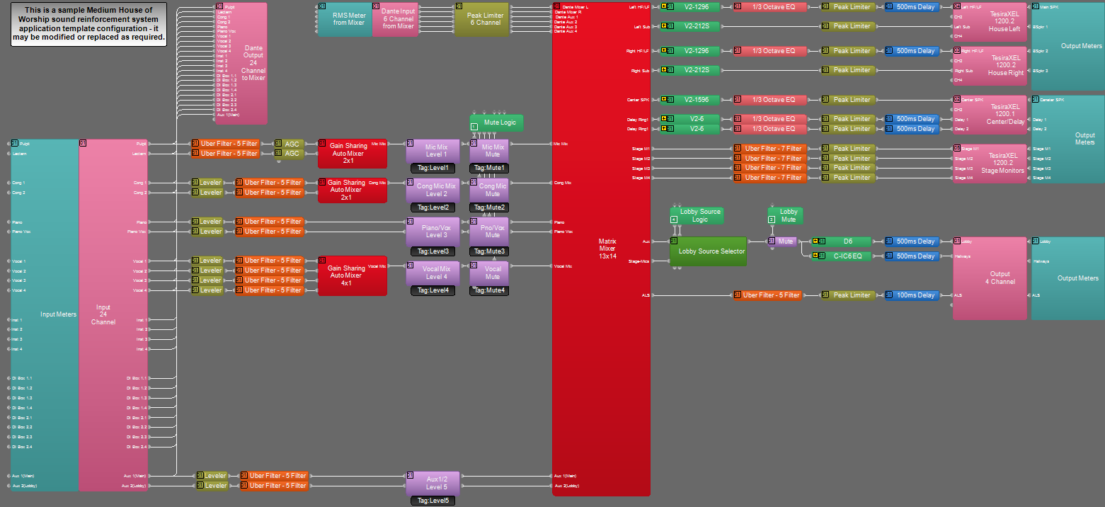
The example file for this application template is set up with all the analog audio I/O, processing, and control points required for the functionality scope, and is nearly ready to load to the hardware system. In the file, the matrix routing is configured to have all source inputs feed to all locations by default. These routes may be changed or modified as needed to fit the specific design application.
The file's Equipment Table is populated with the proper hardware to match the layout, but will need to have serial numbers and proxy host assignments added before loading the file to the system. The Sanctuary and Sound Board TEC-1 devices have a multi-page configuration with a home navigation page and subpages for zone level adjustment. The Lobby TEC-1 is used for individual zone level adjustment and source selection only.
To assist with deployment and commissioning of systems which include Community and Desono speakers, a Tesira Library File (.tlf) has been created. This includes custom blocks with Biamp's recommended EQ curves to optimize the sound the included loudspeakers in this design. The custom blocks have been included in this system design template file. These blocks can also be found in the Processing Library in Tesira software.
The .zip file below contains the example Tesira configuration file for this Medium House of Worship system design.
File Download: Medium House of Worship sound reinforcement system.zip
Networking details
The Medium House of Worship system design will make use of the control, Dante, and AVB network interfaces of the hardware to achieve a fully functioning room environment. To get this design properly running on our hardware, you will need to prepare the control, Dante and AVB sides of the network. This system utilizes a single network switch for all control, Dante, and AVB traffic. For a more detailed guide on how to implement these protocols on a single network switch, please reference our articles on Tesira Network Infrastructure and Using Multiple Networked Audio Protocols.
Tesira and TEC-1 devices will need to be discovered in Tesira software before the configuration can be sent. The PC must have a unique IP address in the same subnet as the Tesira SERVER-IO and TEC-1 devices. All devices are configured from the factory with DHCP or Zero Conf (Link Local) address. If you wish to verify your PC network interface is set correctly, please review the Setting an IP address section. More details of system connections can be found here.
In this application, the Tesira SERVER-IO, Dante mixer, Control PC and TEC-1 devices will be connected through a managed switch. TesiraXEL 1200.1 and TesiraXEL 1200.2 amplifiers will use daisy-chain AVB topology for direct connection to Server I/O.
TesiraXEL offers the ability to daisy chain the network ports, use single cable mode per amplifier, or use redundant AVB ports for signal path resilience.
Daisy Chain and single-cable mode: Control and AVB on both ports. Single-cable connection is supported on port 1 when port 2 is left disconnected. Daisy chain is initiated by connecting a TesiraXEL amplifier or Biamp DSP to port 2. (Amplifiers are in Daisy Chain mode by default. Important: In Tesira firmware version 3.12.0.15 and later, RSTP must be enabled on the Port Mode tab of the Network Settings (Device Maintenance) for each amplifier to allow AVB to pass via Port 2.)
Setup Requirements:
- Control network switch with sufficient ports and/or PoE capable port(s)
- AVB Network ports from Tesira SERVER-IO, TesiraXEL 1200.1 and TesiraXEL 1200.2 daisy-chain
- TEC-1 devices must be connected to the control network switch
- 802.3af (Class 1) PoE injectors or PoE-capable ports must be used to provide each TEC-1 device with 3.2W of power
- Follow our steps to set up a switch for use with multiple networked audio protocols found here
- Follow proper setup steps for discovery and assignment of TEC-1 controllers as shown in system control section of this article
- Connection to network and local PC if Canvas user interface control will be used
After these control, Dante, and AVB network setup steps are complete, you will be ready to send your compiled system configuration to the hardware.
Audio setup
- Follow Gain Structure best practices to set input and output levels of microphones and sources. Input and output gain levels have been left at default settings for integration flexibility of the file. Input and Output metering has been added to assist with setting gain structure within the file. Additional meters can be added to the file as required to allow for additional detail at point along the signal path.
- Properly tap Sanctuary and Distributed speakers to match the provided amplifier's power. This amplifier may be substituted to fit the design application or speaker type as needed.
- Gain Sharing Automixers may be changed as needed to fit the specific design application. In the example file, there are two Gain Sharing Automixers in place for the main platform and choir microphones.
- Level and mute controls have been added to the file prior to the Matrix Mixer. These are added for flexibility to meet the design criteria and tastes of the client or integrator. These level controls have been set with recommended maximum and minimum values in place, but can be adjusted to fit the needs of the space.
- Mute logic has been added to the Sanctuary, Sound Board, and Lobby TEC-1 devices so that the triangle indicator in the TEC-1 indicates the mute state of the selected channel. This will allow for sources to be toggled to mute. The triangle indicates that the corresponding channel is muted. This may be changed or modified to fit the end user control needs.
- The TEC-1 hardware has been configured to control volume levels and mute functions. In the main Sanctuary and Sound Board, the TEC-1 also has mixing controls for all mic mixes being used in the file. There is a TEC-1 controller for the Lobby area that allows for overall zone level adjustment in the lobby only.
- Uber Filters have been added to all input signal paths to allow for any additional equalization as needed to sources. Additional filtering or dynamics blocks may be added or changed as needed to achieve the desired results in the file.
- Graphic equalizer blocks have been added to the file output paths to allow for room tuning and optimization. These may be changed as needed to fit the design application.
- System is designed with L/R/C speaker capabilities including Subs. Routing in the matrix mixer is designed to accommodate a number of different design criteria and may be changed to suit the specific application needs.
- Stage monitor sources have the ability to be sub-mixed separately from the main Sanctuary sources. This functionality may be modified as needed to fit the design.
- Changes to the Matrix Mixer can be made as needed to allow for appropriate sources to feed the Sanctuary, monitor, and distributed zones to fit the system design.
System control
TEC-1 Setup: The TEC-1 wall mounted controllers in this system are a standard Ethernet device and require 802.3af Class 1 PoE. The default network configuration of TEC-1 units is DHCP, so if there is no DHCP server on the Tesira network the units will revert to Link Local (or Zero Conf) addressing schemes (e.g., 169.254.xxx.xxx, netmask 255.255.0.0). Each TEC-1 requires a unique IP address.
The TEC-1 will display "Waiting for Configuration..." on the screen until a configuration file has been loaded to the Tesira SERVER-IO that includes the TEC-1's correct Device ID. The Device ID of the TEC-1 is used to associate the block with the physical TEC-1, and must be configured to match in both the TEC-1 hardware and the configuration file's TEC-1 block. The units in the file are set up with their device ID already set, so you will need to configure the TEC-1 hardware to match. Each ID is shown in a text box next to its associated TEC-1 block in the file. The Sanctuary and Sound Board TEC-1 devices have been set up with a multi-page configuration for mixing specific levels in their appropriate areas. Additional info on utilizing multi-page TEC-1 configurations can be found here. Information regarding RED-1 devices on this page can also be applied to TEC-1 devices.
Control System Integration: The example Tesira configuration file for this application file has been set up to allow third-party control systems to easily control the Tesira system if desired. There are control points for Level and Mute already in place, and more can be added to the file if required. Control points within the file have been left at their default Instance ID tag settings. These tags can be modified if necessary.
Further reading
- Tesira Network Infrastructure
- TesiraXEL Amplifiers - Network Configurations
- Gain Structure
- AGC
- Loudspeaker Equalization
- General Audio Concepts
- TEC-1 Setup and Programming Guides
- TEC-1 and the Mute block
- Using multiple networked audio protocols
- Community V2-1596
- Community V2-1296
- Community V2-212S
- Community V2-6
- Community MX8
- Community House of Worship Design Guide