3-way divisible conferencing space
This system design template shows how Tesira products can be used in a divisible conference room installation. This conferencing space can be divided into three independent spaces, one large combined space, or any combination of two spaces. These rooms are designed to allow participants to host local meetings using local presentation capabilities, make conference calls to remote meeting participants over the phone (VoIP or analog POTS), or use a traditional video conference codec. Each of the three spaces will have identical functionality and capabilities.
In this example, each conference room is designed to include 12 table-mounted microphones, bringing the total count to 36. These microphones leverage Tesira's Acoustic Echo Cancellation (AEC) to achieve optimum speech quality to the far-end participants. Each microphone also has a mute button and a bi-color LED which are wired into logic inputs/outputs in the Tesira system. For sound reinforcement, the conference room is outfitted with both ceiling speakers (for playback of speech audio) and stereo wall speakers (for playback of program audio). The Tesira system will be designed with control points to allow for integration with third-party control systems for various level, mute, and dialing functions.
Room design
Room Functionality Scope: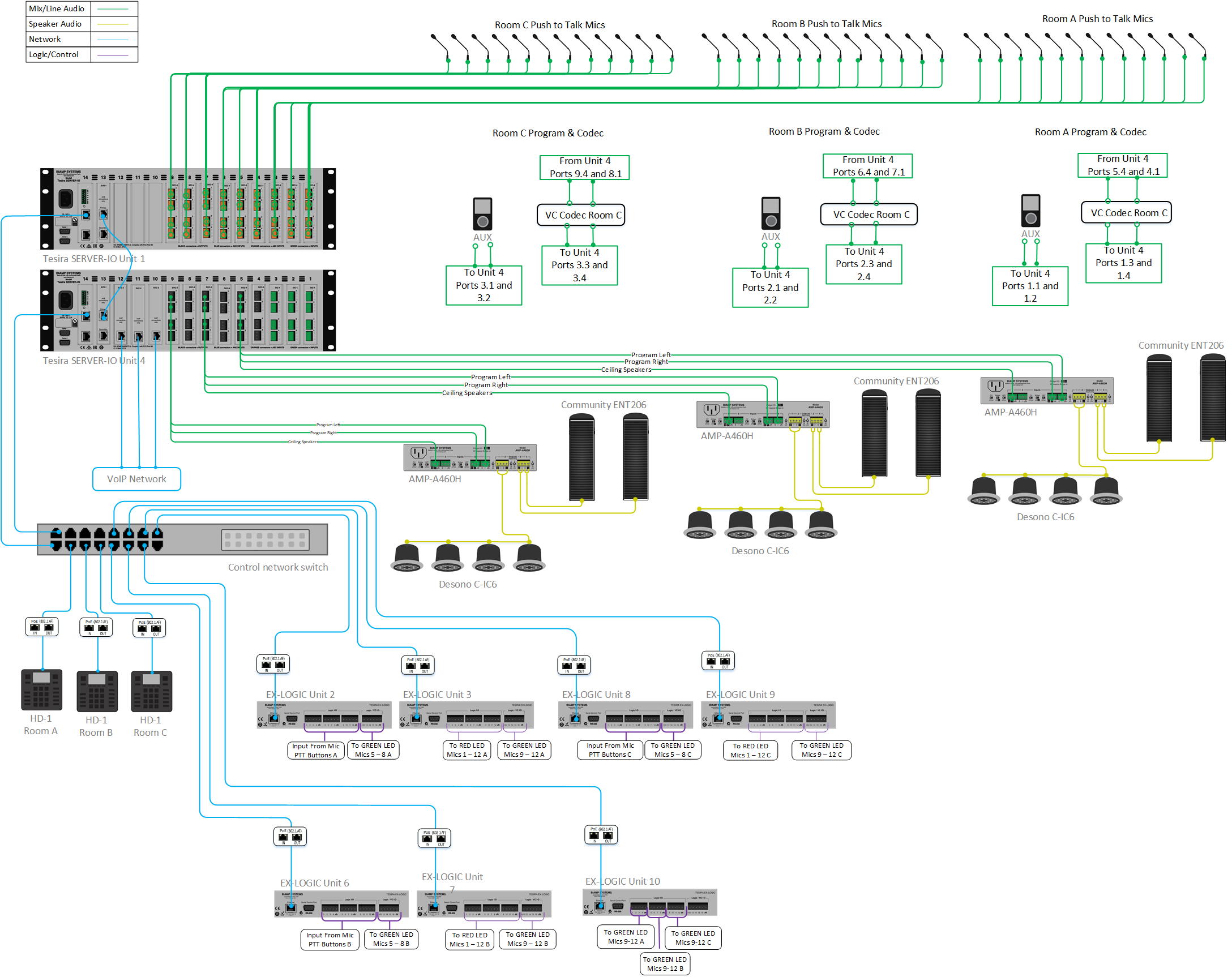
Each room must contain the following:
- 12 table-mounted microphones with push-to-mute functionality and LED mute status feedback from the system
- Connection to building phone system: this system will utilize VoIP
- Video conference codec
- Stereo program source audio inputs
- System control via third-party control system and HD-1 dialers
- 70V distributed ceiling speakers for playback of voice signals
- Stereo speakers for playback of program sources.
Equipment list
Below is a list of Biamp equipment used for this project:
- 1 - Tesira Server I/O with the following card layout
- 9 SEC-4 cards 4 channels (each) of mic/line level inputs with AEC
- 1 AVB card
- 1 DSP card (included when ordering a Server I/O chassis)
- 1 SNC card (included when ordering a Server I/O chassis)
- 1 - Tesira Server I/O with the following card layout
- 3 SIC-4 cards 4 channels (each) of mic/line level inputs without AEC
- 6 SOC-4 cards 4 channels (each) of line level outputs
- 3 SVC-2 cards 2 lines per card for VoIP connections
- 1 AVB card
- 1 DSP card (included when ordering a Server I/O chassis)
- 1 SNC card (included when ordering a Server I/O chassis)
- 3 - Tesira HD-1 Dialer, hardware-based dialer: 12-button dial pad with access to all Tesira telephony functions, PoE-powered (optional)
- 7 - Tesira EX-LOGIC 16 total logic connections per unit can be used as inputs or outputs for microphone mute and LED integration, PoE-powered
- 3 - AMP-460H 4-Channel, 60W class D amplifier; supports both 70V and 100V constant-voltage speaker systems
- 12 - Desono C-IC6 Wide coverage two-way, passive coaxial design ceiling speakers (dispersion angle of 130°) optimized for voice reproduction
- 6 - Community ENT206 Two-way Compact Column Point Source Loudspeaker; 6 LF Drivers, 2 High Frequency CRE arrays, 2-way crossover, 150W continuous @ 8 ohms
Note there is non-Biamp equipment required for this project to include: table-mounted microphones, network switch, PoE injectors and Cat-5 Networking cables. This template assumes that the room combine-and-divide functionality will be controlled via a 3rd party control device.
Example files
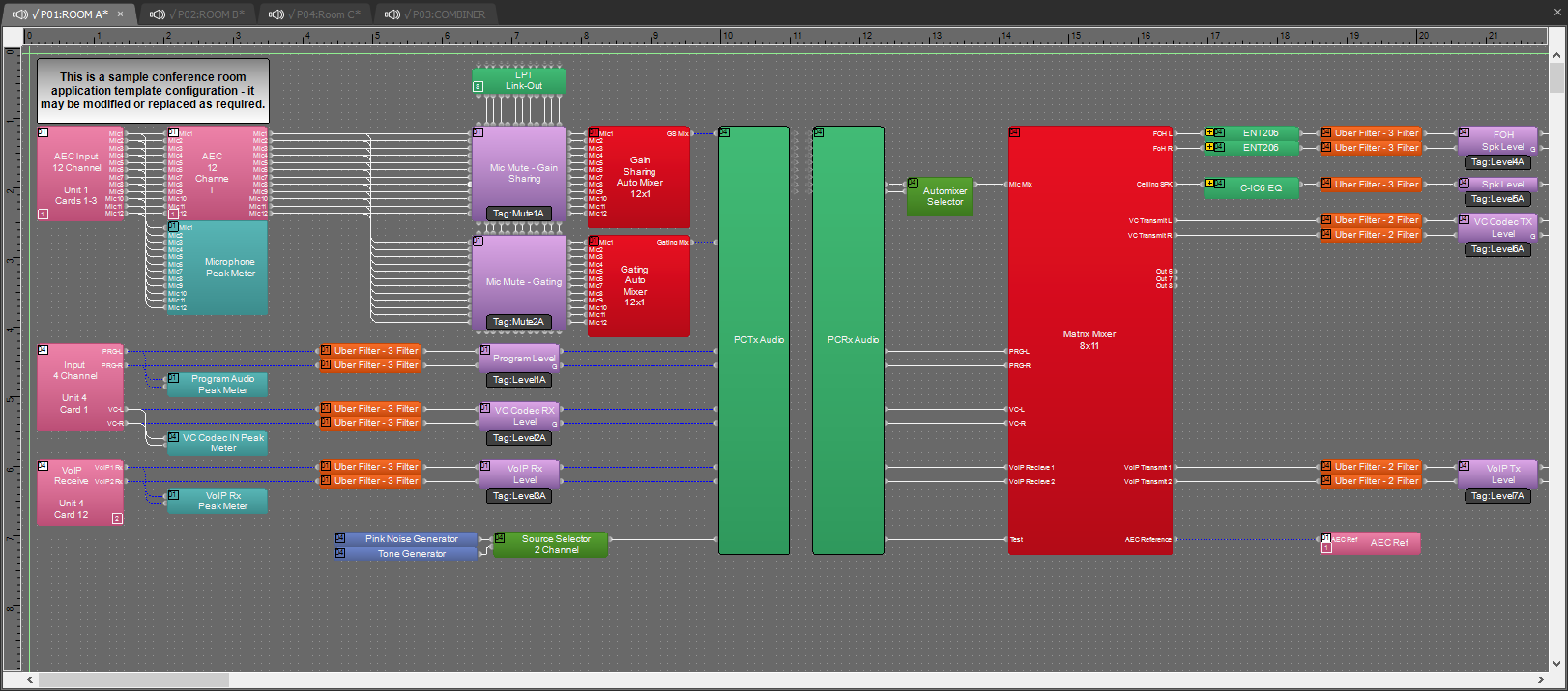 The example file for this application template is set up with all the audio I/O, processing, and control points required, and is ready to load to the system and set up the room gain structure. In the file, the matrix routing is already in place to support the room design requirements. All AEC inputs are located on Unit 1 in the equipment table. The 36 mic inputs are split evenly among the three rooms. Unit 4 in the equipment table handles the program audio, the VoIP lines and the outputs to the stereo speakers and 70V speaker systems.
To support the conferencing needs of the space, mixed-room microphone signals are routed to the VoIP, analog POTS line and USB outputs. The file has both Gain Sharing and Gating Auto Mixers with the ability to select and audition between them for best fit into the application. All AEC references have been made in the matrix mixer for proper echo cancelation of conferencing sources. The file's Equipment Table is populated with the proper hardware to match the layout but will need to have serial numbers and proxy host assignments added before loading the file to system. Currently there is a soft dialer block in the configuration that allows remote dialing into the system during configuration and testing of the VoIP line. If HD-1 physical dialers are to be implemented, the virtual dialer blocks will have to be removed and replaced with HD-1 blocks.
To assist with deployment and commissioning of systems which include the Desono C-IC6 and Community ENT206 speakers, a Tesira Library File (.tlf) has been created. This includes custom blocks with Biamp's recommended EQ curves to optimize the sound of the included loudspeakers in this design. The custom blocks have been included in this system design template file. These blocks can also be found in the Processing Library in Tesira software.
The .zip file below contains the example Tesira configuration files for this conference space application.
File download: 3-way Divisible Conference Space.zip
Networking details
 The conference room application will use the control and AVB network interfaces of the hardware to achieve a fully-functioning room environment. The control and AVB sides of the network must be configured for this design to operate on Biamp hardware. This system is also small enough to be placed on a very small local AV switch with direct AVB connections between devices, but may be integrated into a larger building network that shares larger switches for the control and AVB traffic. For a detailed guide on how to implement in a larger range of network applications, refer to the following article: Tesira Network Infrastructure.
This system will utilize two server-class chassis and these devices may be connected directly with no AVB switch present. Should the system be expanded to include a 3rd Tesira device, an AVB switch will be needed.
Setup Requirements:
- Control network switch with sufficient ports
- 802.3af (Class 1) PoE injector for powering the EX-LOGIC and HD-1 dialers (unless the Control switch provides PoE power)
Audio setup
Follow Gain Structure best practices to set input and output levels of microphones and sources. Input and output gain levels have been left at default settings for integration flexibility of the file. Input and Output metering has been added to assist with setting gain structure within the file and additional meters can be added to the file as required to allow for additional detail at points along the signal path.
Make sure VoIP and/or Analog Telco is set up and the system is ready to make and receive calls. Connect I/O from TesiraFORTÉ to the room VTC system. Be sure to reference audio settings in VTC system to disable AEC, and change mic/line settings as needed. Reference the VTC setup documents as needed. Connect USB to PC for soft codec integration if required; reference the USB interface setup document if needed. Select constant voltage (CV) and bridging on amplifier channels as needed to support room speaker topology.
Reference the AEC best practices documentation and do test calls with the system: ERL values between 0dB and +15dB are optimal.
Level and mute controls have been added to the file pre and post-matrix mixer for flexibility to meet the design criteria and tastes of the client or integrator. These level controls have been left with their default maximum and minimum values in place, but may be adjusted to fit the needs of the space.
The HD-1 hardware has tactile controls for level and mute functions. Note that these control level and mute parameters are on the VoIP or Telco blocks themselves, and cannot be assigned to the standard level controls.
Uber Filters have been added to all signal paths to allow for any additional equalization as needed to sources. It is recommended to use the advanced filters section of the AEC channel processing block for for any high pass filtering needed on conference table microphone inputs. Additional filtering or dynamics blocks may be added or changed as needed to achieve the desired results in the file.
Changes to matrix mixer can be made as needed to allow for appropriate sources to feed the stereo and distributed speaker zones to fit the design application.
VoIP setup
If a VoIP phone line is used, it must be configured to register with the in-house VoIP phone system. Biamp VoIP interfaces have been tested and/or certified to work with the VoIP telephony systems listed here. Biamp VoIP interfaces may also work with other SIP-based VoIP systems, but haven't been tested or certified with those systems.
When integrating Tesira with one of the tested/certified VoIP systems, it is best to follow the detailed instructions in the appropriate article to ensure a successful deployment.
Detailed instructions can be found in the following articles:
- Microsoft Lync / Skype For Business
- Cisco CallManager
- ShoreTel
- Mitel 3300 ICP configuration for a Tesira SVC-2 or TesiraFORTÉ VI
- Avaya Session Manager
- Avaya SES
- Avaya IP Office
- Avaya Communication Server
To configure the VoIP interface open the VoIP Control/Status block configuration dialog to access VoIP settings:
![]()
Click to see configuration dialog.
For VoIP endpoint registration, fill in the required fields in the Network and Protocol tabs of the VoIP Control/Status block:
- Network Tab:
- IP Address / Netmask /Gateway - the VoIP card must have an appropriate IP configuration for the network it is connected to.
- VLAN Tagging - if the VoIP card is on a "tagged" VLAN, this must be enabled and the correct VLAN ID provided. If the VoIP card is on an "untagged" VLAN (or no VLAN), this should not be enabled.
- Protocol Tab:
- SIP User Name - this is usually the extension number that the VoIP interface will use.
- Authentication User Name / Password - the username and password required to authenticate this extension.
- Proxy Vendor - selecting the correct vendor will ensure the VoIP interface correctly tailors its communications to the VoIP system.
- Proxy Address - the IP address of the VoIP proxy server (also known as: VoIP server or Call Manager server).
Much of the above information must be obtained from the customer's IT or VoIP team. The following document was designed to facilitate the process of obtaining this information. Provide this documentation to the IT/VoIP team and ask them to fill it out:
VoIP Checklist Form
Analog phone setup
An analog phone interface may also be implemented with this system in addition to or in lieu of a VoIP system. An STC-2 card will be required and I/O blocks must be added to the files. Each STC-2 card has two lines. For more information about our analog phone lines, see the Tesira documentation.
Microphone mute button and LED logic
For microphone control, assume the microphones used have following features:
- Mute button (setup for "momentary" functionality)
- RED LED for Mute ON indication
- GREEN LED for Mute OFF indication
Depending on the power requirements of the LEDs, an external power supply may be required.
Each microphone will require 3 GPIO pins, one for each feature. With 36 Microphones, a total of 108 pins is required. With 7 EX-Logics in the system providing 16 pins each there will be a total of 112 pins.
Logic I/O Unit and Channel Assignments
Room A:
EX-LOGIC (Device ID 02)
Channels 1 - 12 connect to Mute Buttons for Mics 1 - 12 in
Channels 13 - 16 connect to GREEN LEDs for Mics 5 - 8 in
EX-LOGIC (Device ID 04)
Channels 1 - 12 connect to RED LEDs for Mics 1 - 12
Channels 13 - 16 connect to GREEN LEDs for Mics 9 - 12
EX-LOGIC (Device ID 10)
Channels 1-4 connect to GREEN LEDs for Mics 1 - 4
Room B:
EX-LOGIC (Device ID 06)
Channels 1 - 12 connect to Mute Buttons for Mics 1 - 12 in
Channels 13 - 16 connect to GREEN LEDs for Mics 5 - 8 in
EX-LOGIC (Device ID 07)
Channels 1 - 12 connect to RED LEDs for Mics 1 - 12
Channels 13 - 16 connect to GREEN LEDs for Mics 9 - 12
EX-LOGIC (Device ID 10)
Channels 5-8 connect to GREEN LEDs for Mics 1 - 4
Room C:
EX-LOGIC (Device ID 08)
Channels 1 - 12 connect to Mute Buttons for Mics 1 - 12 in
Channels 13 - 16 connect to GREEN LEDs for Mics 5 - 8 in
EX-LOGIC (Device ID 09)
Channels 1 - 12 connect to RED LEDs for Mics 1 - 12
Channels 13 - 16 connect to GREEN LEDs for Mics 9 - 12
EX-LOGIC (Device ID 10)
Channels 9-12 connect to GREEN LEDs for Mics 1 - 4
For details on wiring the microphone's mute button to the EX-LOGIC see Wiring switches to the EX-LOGIC. For details on wiring the LEDs to the EX-LOGIC see Wiring LED's and relays to the EX-LOGIC.
Control integration
HD-1 Setup
The HD-1 dialer in this system is a standard Ethernet device and requires 802.3af Class 1 PoE. The default network configuration of HD-1 units is DHCP, so if there is no DHCP server on the Tesira network the units will revert to link local addressing (169.254.xxx.xxx, netmask 255.255.0.0) schemes. The HD-1 will display "Waiting for Configuration..." on the screen until a configuration file has been loaded to the Server associating it by its Device ID. The Device ID of the HD-1 is used to associate the block with the physical HD-1 and needs to be set in 2 places: the HD-1 processing block and in the HD-1 hardware. The HD-1 must be associated with a specific telco card in the software. The HD-1 and telco card will then share an identification number seen at the bottom right corner of the blocks. The buttons on the HD-1 have fixed functionality and cannot be programmed in the software to perform specific functions. The complete HD-1 configuration article can be found here.
Control System Integration
The example Tesira configuration file for this application file has been set up to allow third-party control systems to easily control the Tesira system. There are control points for Dialing, Level, Mute, and Mic Logic already in place to allow for you to use as it as-is, or add to as needed to suit the needs of the client.
Control points within the file have been noted with an additional text box showing their default instance ID tag. These tags can be changed as needed to suit the programmer workflow or standardization.